In fig. 1.2 you see an exemplary three-stage protection circuit of DC power supply circuit 24 V DC from surges. The protective diode has excellent switching parameters (response speed and repetition of restriction level values), but mounted independently it may be damaged, and usually needs protection itself. Its single crystal structure is not able to withstand the effects of a strong energy surge.
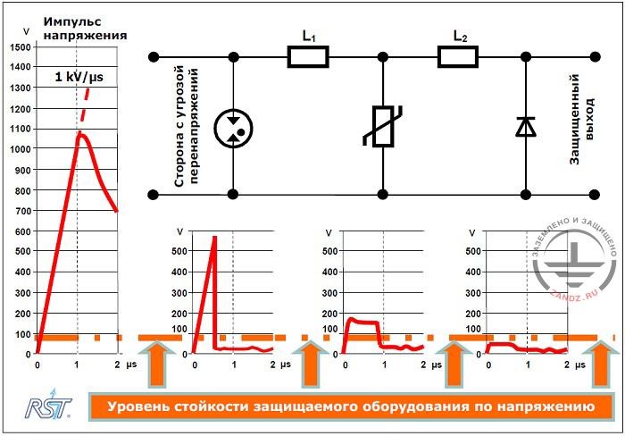
Fig. 1.2. Cascade structure of surge protection: surge arrester - surge voltage-variable resistor- diode
Импульс напряжения – voltage impulse
Сторона с угрозой перенапряжения – side with the surge voltage threat
Защищенный выход –protected output
Уровень стойкости защищаемого оборудования по напряжению – voltage sustainability level of the protected equipment
To support the branch with a diode the previous protection stage based on ZnO voltage-variable resistor, which is able to bring greater energy to the ground than a diode, is used. For the purpose of a proper co-ordination of protective parameters, the diode and the voltage- variable resistor are separated by a special element of L2 (in this case inductance is applied). Due to this, when the surge current flows in the result of overvoltage suppression by the diode, then the voltage will appear at the terminals of the voltage-variable resistor
Uvoltage-variable resistor = Udiode +L2 di / dt,
Where: di / dt - rate of pulse current growth (overvoltage current).
By selecting appropriate inductance value L2 you can control the voltage on the voltage variable resistor, so it would fit the surge suppression process before a diode is subjected to damage.
A similar situation occurs in the cascade arrester - voltage-variable resistor. It is known that if to include the arrester into operation, thanks to its excellent energy parameters it increases the ability to exhaust the destructive power of surges through the protective device. The element L1 is selected in such a way that a relatively slowly coming on arrester would start to act before critical parameters of the voltage-variable resistor are exceeded.
The cascade circuit shown in Fig. 1.2 allows connecting in this example a very high speed of action with respect to the sensitive protective diode with the ability to drain very large surge currents through the arrester and the voltage-variable resistor, which are characterized by the highest suppression levels and slower response.
1.4. Classification of surge arresters
Devices for limiting overvoltages used in low voltage distribution networks (up to 1000) inside building sites include at least one non-linear element and in accordance with the regulatory requirements they must be subjected to testing of class I, II or III.
From the point of view of various characteristics of surge arresters, determined during impact testing, these devices are divided into:
Surge arresters Class I (formerly Class B) - The required protection properties for this group guarantee surge arresters on the basis of a gas arrester, on the electrodes of which there occurs a spark breakthrough, turning into an arc discharge in case of an over-voltage shock. In this type of arresters, the value of the reduced voltage is equal to the operation voltage and depends on the rate of surge voltage growth. The values of nominal surge current that can flow through the system of arresters of class I, without causing damage, correspond to current intensity values, which can occur in natural conditions during a thunderstorms (in accordance with the requirements of lightning protection). Typical levels of protection of class I arresters does not exceed 4000 V.
Surge arresters Class III (formerly Class D) - voltage protection level is normally 1500 V, 1200 V or 1000 V. Class III arresters are subject to tests, performed by the combined impact of: voltage 1.2 / 50 ms and then current 8/20 ms. The highest values of the tested voltage is 20 kV 1.2 / 50 microseconds, and the tested current - 10 kA 8/20 ms. The provide protection of devices from the effects of direct, close and distant atmospheric discharges (a few hundred meters from the object), from induced surges in equipment inside buildings, as well as switching surges that occur in electrical equipment inside the construction site.
Direct lightning strikes or discharges occurring in the immediate vicinity of them cannot be excluded under natural conditions. This leads to the fact that class III arresters often interact with class I limiters and II, forming multi-stage protective systems in electric devices. Basic circuit of connection of successive steps of arresters is shown in Fig. 1.1.
The main properties of different classes of arresters, as well as the approximate places of their installation are presented in Table 1.1.
| Table 1.1. Basic information about surge arresters that meet different classes of shock impacts. | ||
|---|---|---|
| Arrester class | Characteristics of the arrester | |
| Class I (B) | Application |
|
| The main test procedure |
|
|
| Main technical data |
|
|
| Class II (C) | Application |
Surge limit between:
|
| The main test procedure |
Basic testing:
|
|
| Main technical data |
|
|
| Class III (D) | Application |
Surge limit between:
|
| The main test procedure | Testing by nominal shock voltage-current 1.2 / 50-8 / 20. | |
| Main technical data |
|
|
| I, II and III - designation of classes according to IEC 61643-1 with 1998.02 B, C and D - designation of classes according to DIN VDE V 0675 Teil 6 |
||
Related Articles:
 ZANDZ SMS-NEWSLETTER
 5. Reference book on basic parameters and types of surge arresters on the example of the LEUTRON element base