The second part of the article "Lightning protection at a construction site"
Do not rush with the measuring of ground resistance of the foundation made. All recommendations about its use as a grounding device are bacsed on the fact, that the water-repellent concrete drains the moisture from the ground together with the salts that have been dissolved in it. In the result, the reinforcement bars of the foundation occur in the same environment, as those placed directly in the ground. Moisture diffusion from the ground to the concrete takes a lot of time. It is better to wait 1-2 months for control measurements.
The measuring method of ground resistance is well known by multiple manuals. As a rule, there is a scheme, presented in fig. 1.
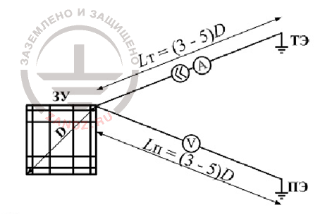
Fig. 1. Typical measuring scheme of the building foundation ground resistance
The circuit of the measured current is completed via an auxiliary current electrode (CE) and the voltage at the foundation is measured relative the potential electrode (PE), remoted to 3-5 maximal dimensional sizes D, where the potential is slightly different from zero. The quotient of the measured voltage to current gives the sought ground resistance.
There is a serious problem behind the external simplicity of the scheme.
Recently, to save up free space, it is recommended to place the current and potential electrodes on one straight line (fig. 2).
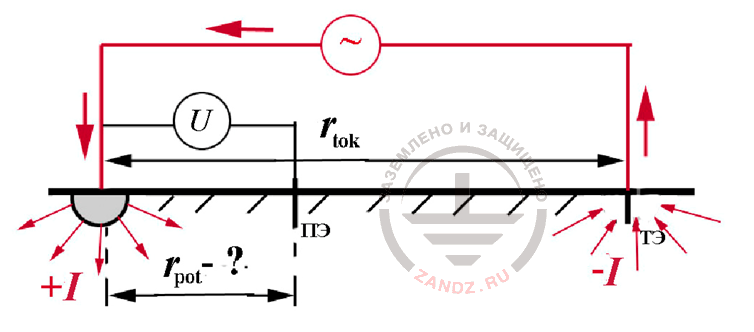
Fig. 2 The scheme with the arrangement of auxiliary electrodes on a straight line
Since the currents in the measured ground electrode system and in the auxiliary electrode (CE) are oppositely directed, then there will be a point of zero potential on a straight between them (here we see a complete analogy with the potential of electric charges of equal in size and opposite in charge). It is recommended to place the potential electrode around this zero potential point. For example, in some foreign factory instructions, it is prescribed to have rpot = 0,62rtok. Detailed computer expertiment (fig. 3) showed, that the best result is obtained by the measuring at the position of the potential electrode right in the middle of the straight, connecting the measured foundation with the current electrode. Even for very large buildings, the fault of measuring doesn't exceed 10% here, not looking at the fact that the distance to the electrode CE did not exceed 0,5D instead of the prescribed normative values of 3-5 D. Detailed quantitative analysis of the scheme is presented in the book "Questions of practical lightning protection", which was published last year by the initiative of the ZANDZ.com project.
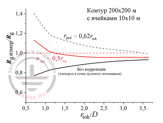
Fig. 3. Measuring fault of the building foundation ground resistance in the correlation to the distance D at the different location of the potential electrode
Контур 200 на 200 м с ячейками 10 на 10 м – contour 200x200 m with cells 10x10 m
Без коррекции – without correction
Электрод в точке нулевого потенциала – electrode in zero potential point
E. M. Bazelyan, DEA, professor
Energy Institute named after G.M. Krzyzanowski, Moscow
Read more "3. What lightning rods are required at the construction site?"
See also:
- Lightning protection of residential and public buildings (article by professor E.M. Bazelyan)
- Free webinars for designers of grounding and lightning protection
- Soil resistivity chart
- Grounding and lightning protection projects in dwg, pdf formats
- Free consultations and assistance in calculation of grounding and lightning protection
Related Articles:
 Lightning protection of residential and public buildings - answers to frequently asked questions in the design
 Lightning Protection of Large Territories: Parks, Grounds, Plant Territories. Page 1
 Lightning Protection of Large Territories: Parks, Grounds, Plant Territories. Page 2
 Lightning Protection of Large Territories: Parks, Grounds, Plant Territories. Page 3