Creating a grounding arrangement in a city is complicated by limited space available. The territory around the building is usually covered with asphalt or occupied by neighboring buildings. In most cases, open areas (such as flower beds or lawns) are pretty small. Even if large-scale construction works are provided during the design, numerous underground utilities installed under the ground do not allow installation of the grounding arrangement in close proximity. However, designers still have several possible options.
1. Features of compliance with lightning protection regulations
First, determine constraining requirements to the grounding arrangement, especially if it is used as an external lightning protection. For example, when using a lightning grid or metal roof as a lightning arrester, provide a grounding circuit along the facility's perimeter (RD 34.21.122-87, item 2.11, item 2.26).
This problem can be partially solved using two methods:
- Using nearby high-rise facilities as natural lightning arresters (there are usually many of them in cities). In this case, no strict structural requirements to the grounding arrangement are applied: only the protective grounding is required without the lightning protection.
- Design the lightning protection using rod or wire lightning arresters. In this case, local grounding is sufficient for each current collector, which consists of 3 or 2 vertical electrodes spaced at 5 m (RD 34.21.122-87, item 2.2d, item 2.26) for protection Levels II and III, respectively.
2. Low resistance of the grounding arrangement and challenging soil types
The problem worsens when low resistance of the grounding arrangement (e.g., 2 Ohms) is to be ensured or when soils have high resistivity. Both factors increase the size of the area necessary to install the lightning arrangement manifold.
Possible solutions:
- Using deep-laid modular grounding electrodes, thus ensuring that the soil layer with lower resistivity (e.g. water-bearing) is achieved. In these cases, it is essential to use corrosion-resistant materials (copper-plated, zinc-plated, stainless steel, or copper). Ready-made sets are also available (e.g., ZZ-000-015, ZZ-000-030, ZZ-000-045, ZZ-000-115, etc.). If the manufacturing quality is ensured, this grounding electrode type allows using deep-laid electrodes 10 to 20 m long in mixed soils using special equipment. Installation of grounding electrodes 30-40 m long requires good soil, special striking tools, and supplementary equipment.
- Installation of the grounding arrangement in basements, if they are not intended for use as part of the lightning protection system. The service floor usually does not have high requirements to the room appearance, while underground utilities under the building are pretty rare. These aspects often allow installation of several deep-laid modular grounding electrodes in the pockets of the foundation plate. Low total resistance can be achieved by interconnecting them. However, if the grounding electrode is intended for the lightning current flow, its location inside the building is prohibited by regulatory documents.
- Using electrolytic grounding electrodes, which can reduce the resistance in permafrost and high-ohmic soils by 8-12 times compared to conventional electrodes. Such arrangements can be horizontal or vertical. Their lengths vary 2 to 15 meters. The main condition is location of electrodes at the distance of at least 3 meters from the building foundations.
- The reinforcement of reinforced concrete foundations can be used as natural grounding electrodes as much as possible (EIC, item 1.7.54, item 1.7.109, SO 153-34.12.122-2003, item 3.2.3.3, RD 34.21.122-87, item 3.7). This allows avoiding additional installation if the reinforcement in the foundation forms continuous metal coupling.
- Location of the grounding arrangement at the distance up to 2 km from the facility (EIC, item 1.7.106). This option is possible if there is an appropriately sized area within 2 km radius.
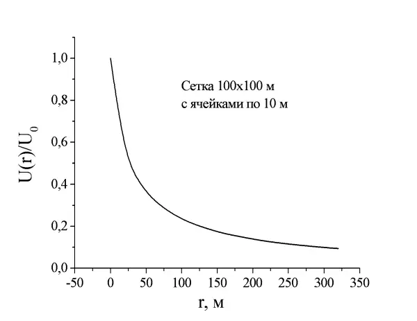
- Soil artificial processing or replacement with a low-resistivity material (e.g., coke fines ~2.5 Ohm·m according to GOST R ISO 10143-2016). This may significantly reduce the area required for the installation of the grounding arrangement. In this case, calculate the replacement volume taking into account 1.1R length of the grounding electrode, the so-called working zone of the electrode, where the main portion of current flows.
Summary
Various solutions are available that allow achieving the required grounding parameters even in the case of dense urban development. It is better when the optimal solution are chosen and the lightning protection and grounding system calculations are made by specialists. If you need additional consultation, contact the ZANDZ Technical Center.
Related Articles:
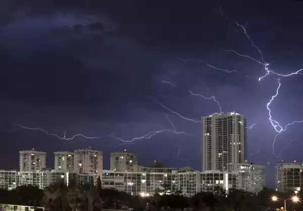
 Is Lightning Dangerous in a Large City?
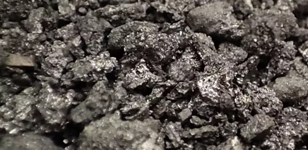 ZANDZ Coke Fines to Reduce Grounding Resistance
.jpeg) Exemplary Design of Grounding System for a Control Station Using Coke Fines
Exemplary Design of Grounding System for a Control Station Using Coke Fines