|

Grounding in lightning protection Answers to all questions
- Заземление в молниезащите – grounding in lightning protection
- Семинар четвертый- the forth seminar
- Проф. Э.М. Базелян – Professor E.M. Bazelyan
- ОАО «Энин» Москва – “Enin” JSC, Moscow
We begin the seminar, and we will hold it from two points. I'm from Moscow and Alexei Rozhanka from Novosibirsk will comment on the questions you ask.
- Yes. Good afternoon!
- Good afternoon! The question we are going to discuss today is the most fundamental for me. Generally speaking, 50 years ago I came to lightning protection, being engaged in the processes of grounding. On my way here, I got a call about another experiment, which is held in the soil and is connected with the runoff of high currents. This work never stops because it seems that like grounding issues related to the unlimited size of the land - are endless, and the problem itself is also endless.

Grounding resistance of a lightning rod
Величина сопротивления заземления молниеотвода практически не влияет на эффективность его работы, тем не менее, это один из наиважнейших параметров во внешней и внутренней молниезащите – The value of lightning rod ground resistance practically doesn’t affect its efficiency, still, it is one of the most important parameters in external and internal lightning protection
Though, if we talk about how grounding resistance affects the efficiency of a lightning rod, the answer should be as follows: - it almost doesn't affect it. Many different laboratories have not tried to see if the grounding resistance affects the efficiency of a lightning rod, but the answer to this was always the same. Within reasonable limits, this resistance does not affect the efficiency of lightning protection. Nevertheless, the processes of current spreading in the ground are crucial for very many things. First and foremost, this is for the safety of people and secondly, although it may be even a more important question - the question of how microprocessor equipment and machinery, which is exposed to electromagnetic field of the lightning current will act. Basically, through the ground. And we will study these questions.

The required number of grounding devices
- Для заземления в электроустановках разных значений и напряжений, территориально сближенных, следует, как правило,применять одно общее заземляющее устройство – For grounding in electric installations of different values and voltages, territorially close, one common grounding device should be applied as a rule.
- Заземляющее устройство защитного заземления электроустановок зданий и сооружений и молниезащиты 2-й и 3-й категории этих зданий и сооружений, как правило, должны быть общими - Grounding device of protecting grounding of electric installations of buildings and lightning protection of the 2 and 3 category of these buildings and constructions should , as a rule, be common.
I want to say such a thing. The data I will give should have been checked by a direct experiment in the field. But experiments with the operation of grounding devices are much more complex. Therefore, nobody can hold a large number of experiments in the field, neither in Russia nor in other countries. Those experiments which I will show you, are mainly numerical experiments. They are made by the set of computer programs that we developed at the Electrotechnical Institute to the name of Kryzhanovsky specially for this purpose. I am confident in the reliability of these programs and in the results that we will show you. But I want you to think about the following during the seminar. I'll tell you about the results in numerical calculations, but I won't tell about the calculations themsevles today. Because we assume, if this is important for you, to hold a workshop seminar on the methodology of calculation of grounding devices. This workshop will be held in the case, if you say - yes, we need such a workshop! But please consider one thing. Today's

Soil resistance
Удельное сопротивление грунта – Soil resistance
|
Soil type
|
Resistance, Ohm*m
|
|
Sand (at the temperature higher than 0 C):
Waterlogged by ground waters
Moderately watered
Moisture
A bit moisture
dry
|
10-60
60-130
130-400
400-1500
1500-4200
|
|
Clay loam:
Waterlogged by ground waters (at the temperature higher than 0 C)
Frozen layer (at the temperature -5 C)
|
10-60
60-190
|
|
Clay (at the temperature higher than 0 C)
|
20-60
|
|
Peat
at the temperature about 0 C
at the temperature higher than 0 C
|
40-50
1040
|
|
Black soil
|
10-55
|
|
Alkaline soil (at the temperature higher than 0 C)
|
15-25
|
|
Pit gravel
Dry
wet
|
|
|
Granitic subsoil (small alkaline soil, coarse sand)
(at the temperature higher than 0 C)
|
5500
|
|
Granite base (at the temperature higher than 0 C)
|
22500
|
And now let's come back to the actual topic of the seminar. In order to calculate a ground electrode system, we must know soil resistance. This parameter, the value of which is so approximate, you can't even imagine. This chart, which I am showing you was taken from the official, methodological guidelines that had been published in Russia. You see, the numbers for the same soil range several times, soil resistance may vary up to 5 - 6 times depending on conditions and on the measurement location. Although the type of soil is approximately the same. And when you want to calculate or design some lightning protection devices, grounding devices. You have to solve the problem.

How deep the current penetrates into the ground?
- Насколько глубоко проникает ток в землю – How deep the current can go into the ground?
- Ответ – «бесконечно далеко» ничего не дает инженеру, надо знать какая глубина слоя влияет на сопротивление заземления – A response “endlessly deep” gives nothing to the engineer, he needs to know what depth of the layer affects the grounding resistance
- Diagram on the right - Полоса длиной 100 м на глубине 5 м – A tape 100 m long and 5 meters deep
- Толщина верхнего слоя грунта, м – Thickness of the top soil layer, m
- Diagram on the left - Полоса длиной 10 м на глубине 5 м – A tape 100 m long and 5 meters deep
- Толщина верхнего слоя грунта, м – Thickness of the top soil layer, m
- Ток реально проникает в грунт на глубину- the current really goes to the ground to the depth of
And for what soil resistance you will calculate it. It is noy enough to measure ground resistance on the surface, it won't give you anything, because lightning current spreads in the ground and this spreading captures quite deep soil layers. If you ask what these layers are, then the answer will be formal - to infinity. That is, the entire volume of ground is used in the process of soil spreading. For design calculations it is important to understand where is the end of the border at which the current spreading is no longer affecting its resistivity, grounding resistance of the ground electrode system. How to answer this question? Generally speaking, I can not imagine any other answer than this. It was necessary to take a ground electrode, place it in a two-layer environment, and then take two-layer this border and remove it, remote it deep into the ground. And look at what distance the ground resistance, the ground electrode becomes unresponsive to the position of this boundary. Such experiments are impossible in nature, but their can be done numerically. And I showing you the results of these numerical experiments. I took a horizontal bus 10 meters long and saw that its grounding resistance ceases to depend on the depth border, when the border is distanced from the surface to about 10 meters. In this case, the difference between the resistance that would be in clean ground and the one recieved differs within 10% approximately. So what do we get? We need a ten-meter-bus and a ten- meter-depth. This is curious. Now I do the following. I take a bus one hundred meters long and do the same. And I see that now I have to distance the soil down not for 10 but 100 meters. That means that the current spreading is significant for ground resistance to the depth that corresponds to the size of the grounding device, the dimensions of the bus. Working with a three-meter-bus, I need soil depth to be approximately three meters. A hundred-meter bus - it is necessary to go down to 100 meters.

Ground contour in the form of a horizontal mesh
- Diagram on the left - Сетка 10*10 м длиной 10 м на глубине 0,5 м – Mesh cage 10*10 10 meters long 0,5 m deep
- Толщина верхнего слоя грунта, м – Thickness of the top soil layer, m
- Контур заземления в виде горизонтальной сетки – Grounding contour in the form of a horizontal mesh
- Глубина проникновения тока сопоставима с длиной диагонали контура – The depth of current’s penetration is comparable to the contour diagonal length
- Diagram on the right - Сетка 10*10 м длиной 100 м на глубине 0,5 м – Mesh cage 10*10 100 meters long 0,5 m deep
- Толщина верхнего слоя грунта, м – Thickness of the top soil layer, m
And if I now move on to more complex details. I took a contour, that presents itself a mesh. Mesh of horizontal buses. Such contours are carried out at large factories, refineries, power plants, substations. I took the mesh of only 10 * 10 meters. And look, with the depth of appoximately fifteen meters, the soil ceases to affect grounding resistance of the mesh. And what 15 meters is? It is approximately the length of the grounding contour diagonal. Now we take another mesh, 100 * 100 meters. And now a look, I get the same effect when I lower the soil border, up to about 150 meters. It means, it is subject to a rule, the maximum size of the grounding device determines the depth at which the ground electrode functions. And now we face a question. It is not a problem to study the soil on the depth of 5 - 10 meters. After all, I'll drill and take a sample of the soil at this depth. But if I need to know the soil state at the depth of 150 - 200 meters, and even more, there are no other possibilities, except one - an opportunity for geological exploration, I won't have it. And in this situation whether I want or not, I have to use the methods of geological exploration of ground surface. It's a hard work, approximate work. And this is the only way you can only find out the idea of how the characteristics of the soil at this depth changes. That is why the design calculations grounding over a large area turns out to be very approximate. And the only thing I can do in this case, is to design, build this ground electrode system. And then review what I get. There are almost no other variants. But from the analysis that I have now shown you, the following things arise.

Artificial treatment of top soil layer
- Искусственная обработка верхнего слоя грунта –ground top layer artificial treatment
- Сетка 10*10 м длиной 100 м на глубине 0,5 м – Mesh cage 10*10 100 meters long 0,5 m deep
- Толщина верхнего слоя грунта, м – Thickness of the top soil layer, m
Based on the analysis of this analysis, there are two very important applied problems. The first applied task: if you open IEC and read what to do in high-tension soils. The IEC recommends you to hold a chemical soil treatment. If you can't do the chemical treatment of soil, you have a second opportunity. Remove the soil and put more highly conductive soil instead. Both situations are generally associated with high material costs. And you won't be able to replace the soil for a great depth, so won't you be able to treat the soil to the same great depth. Therefore, it is important to see what would happen if I carry out an artificial ground processing and change its resistivity. For example, my main soil had ground resistivity of 1000 Ohm m. Lousy soil. Now I either took the top layer off, or replaced it with, say, black soil or humus. Or I had a chemical treatment of the soil to change its resistance. Let the soil change its resistance tenfold after this chemical treatment, and instead of 1000 ohm meters, I now have 100 ohm m. Let's see now how it affects the ground resistivity, the ground contour, which is 100 meters long and wide and is made of mesh 10 * 10 meters. That is, it is an ordinary grounding contour. Look what we get! I treated the soil for 1 meter deep, reduced the ground resistance tenfold, it became only 3.5 ohms instead of the desired 0.5 ohms. That is, I reduced soil ground resistance tenfold and very slightly changed the grounding resistance of the device, which is in this soil. If I treat 10 meters of soil which is totally unrealistic, then the grounding resistance will be 4 times different from the perfect one. It means, that this treatment to a great depth, it doesn't change the grounding resistance of the grounding device too much, if this grounding device has a large area.

Artificial treatment of top soil layer, mesh 10x10
- Искусственная обработка верхнего слоя грунта –ground top layer artificial treatment
- Сопротивление заземления, Ом – grounding resistance, Ohm
- Сетка 10*10 м длиной 100 м*100 м на глубине 0,5 м – Mesh cage 10*10 100*100 meters long 0,5 m deep
- Толщина верхнего слоя – Top later thickness, m
- Обработанный верхний слой = 100 Ом*м – Treated top layer=100 Ohm*m
- Удельное сопротивление основного грунта , Ом*м – Main ground resistance, Ohm*m
The padding which I am treating is also of a great importance. If my padding is high-voltage, if its resistivity is 2000, 3000, 4000, 5000 ohm m, then the treatment of the top layer of soil to a depth of, say, 3 or 5 meters, won't give us a lot. My grounding resistance is at the level which is shown here, instead of 0.5 ohms, which we were supposed to get if the soil was homogeneous. That means, that the surface soil treatment has a very small impact on the grounding contour of a great area, and any decent effects can be achieved only in one case.

Artificial treatment of top soil layer, contour 10x10
- Искусственная обработка верхнего слоя грунта –ground top layer artificial treatment
- Сопротивление заземления, Ом – grounding resistance, Ohm
- Контур 10*10 м на глубине 0,5 м – Contour 10*10 0.5m deep
- Толщина верхнего слоя – Top later thickness, m
- Обработанный верхний слой = 100 Ом*м – Treated top layer=100 Ohm*m
- Удельное сопротивле ние основного грунта , Ом*м – Main ground resistance, Ohm*m
If you have a localgrounding contour and its dimensions are small. If you treat the soil on the grounding contour, for example, at a residential cottage, where all the dimensions of the ground electrode are - 10 * 10 meters, approximately. You can get quite a decent result here. But if you think about chemical processing of a large surface, that's not that real. I'd like to draw your attention to the following. Todaydifferent companies offer chemically -active electrodes that treat the outer surface of the soil and the depth of this treatment is not too great. If these are ground electrodes of small extent, for example,3 meters long approximately, then in this case you can get quite a good result. But if you made a long extended ground electrode system of these grounding devices, then the effect will probably be insignificant.

Soil climate changes
- Климатические изменения грунта – Climate soil changes
- Сопротивление заземления - Grounding resistances, Ohm
- Горизонтальный электрод длиной на глубине 1 м – Horizontal electrode …m long 1 meter deep
- Супесчаный грунт 350 Ом*м – Sandy clay soil – 350Ohms *m
- Дата измерений – Date of measuring
Now the other side of the same case. It's climate change of soil state. An example of this change is shown in this diagram. For soil with the resistivity of 350 ohm m in Moscow region. These measurements began last summer, in June, and ended in winter. Look, the range of ground resistance changes by a 3-meter-bus was approximately twofold. How does it happen? It happends due to two things. The first thing is- in summer during the dry season, the moisture leaves the soil and the grounding resistance increases. In winter the ground freezes in central Russia, to approximately 1.5 meters and this frozen ground again leads to the fact that the grounding resistance increases. And now the question is, what is the effect?

Dependence of the effect on the length of the horizontal bus
- Зависимость эффекта от длины горизонтальной шины - Dependence of the effect on the length of the horizontal bus
- Кратность роста сопротивления заземления – Divisibility of grounding resistance growth
- Шина на глубине 0,5 м – Bus 0,5 meters deep
- Глубина мерзлого слоя 1,5 м – Depth of the frozen layer 1,5m
- Длина горизонтальной шины, м – Length of the horizontal bus, m
Change of the surface soil layer resistance, how does it affect ground resistance on the size of ground electrodes. Example: I am watching the extended bus. This extended bus has a length that varies from about 1 meter to 100. And there happened a climatological changes in soil resistance. Due to the fact that the soil was frozen to the depth of 1.5 meters, my ground resistance changed tenfold. The question is, how will the ground resistance of the ground electrode system change? Look, if this bus is short, then the change is almost the same. The resistance of the soil has changed tenfold, and the resistance of the ground electrode system also changed tenfold. But asthe bus length increases, the multiplicity of ground resistance change is reduing all the time. And for a 100-meter-bus, for example,at the change of resistivity of the ground electrode system in 10 times, the grounding resistance of the longest 100-meter-bus only changed fivefold.
|
 Lightning protection of residential and public buildings - answers to frequently asked questions in the design


 Lightning Protection of Large Territories: Parks, Grounds, Plant Territories. Page 1
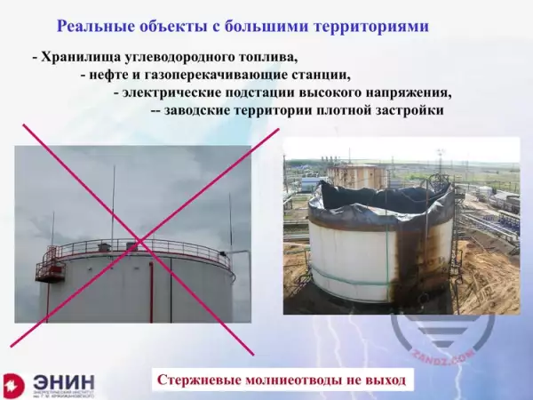
 Lightning Protection of Large Territories: Parks, Grounds, Plant Territories. Page 2
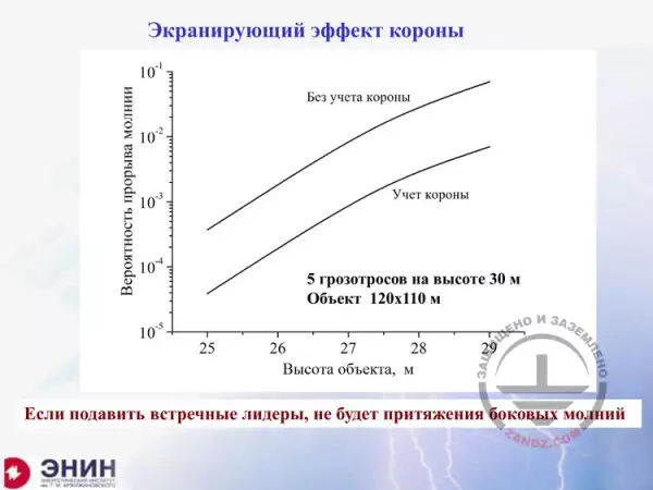
 Lightning Protection of Large Territories: Parks, Grounds, Plant Territories. Page 3


