
E. M. Bazelyan, DEA, professor;
Power Engineering Institute to the name of G.M. Krzhizhanovsky , Moscow;
recognized Russian expert in the field of grounding and lightning protection.
The Russian practice of lightning protection has been successfully using reinforced concrete foundations of buildings as grounding devices for a long time. Even their gas-tar waterproofing does not prevent this. With the soil moisture above 3% and the area of an underground part of the foundation being more than 900 m2 , it can drain the lightning current to the ground. Particular requirements to the grounding resistance in the Russian standards for lightning protection do not imply any requirements to foundations. However, this issue may become important when the building foundation is used as a grounding device for any other purpose than, e.g. to provide electrical safety. In this case, its grounding resistance should not exceed the rated value which may be not available in the soil where the foundation is installed. In such conditions, we often recommend to arrange the grounding circuit along the external perimeter of the building. This circuit is coupled with the embedded features and the reinforcement of the foundation by means of a metal. It is also recommended to attach current collectors thereto to transport the lightning current to the ground. It is clear that in such conditions, the circuit should nearly abut the foundation, usually under a pavement or a perimeter walk.
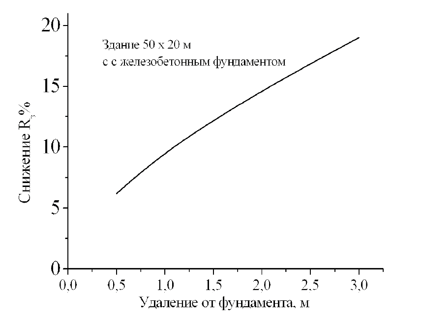
Снижение R, % - R reduction, % Здание 50 х 20 м с железобетонным фундаментом - Building 50 x 20 m with a reinforced concrete foundation Удаление от фундамента, м - Distance from the foundation, m
It is feasible to evaluate the efficiency of the external grounding circuit to reduce the grounding resistance. The method for such calculations has been tried and tested and allows obtaining reliable results. The provided figure shows the percent relationship between the resistance decrease and the distance, by which the external grounding circuit from the horizontal grounding bar is spaced from the building foundation with dimensions 50 x 20 m. The used grounding bar depth is 0.7 m, and the soil grounding resistance does not impact the calculation result.
The circuit installed directly under the perimeter walk at the distance of 0.5 m from the foundation is low-efficient and can reduce the grounding resistance within 5% only. By installing the circuit under the pavement at the distance of 1.5 m from the foundation, we can reduce the grounding resistance by about 12-13%, which is within the error in most cases. To achieve reduction in the grounding resistance by at least 20%, we have to space the circuit from the foundation to about 3 m. To do this, we often have to install it under the road coating, which is a very hard task to organize. We do not need to do this without any particular reason.
Related Articles:
 Lightning Protection of Large Territories: Parks, Grounds, Plant Territories. Page 1
 Lightning Protection of Large Territories: Parks, Grounds, Plant Territories. Page 2
 Lightning Protection of Large Territories: Parks, Grounds, Plant Territories. Page 3