July 13, 2017
All high-rise buildings should have a reliable lightning protection. But there are facilities with special requirements in terms of lightning protection. And they are not always about higher reliability. Sometimes, good elaboration of the design and highest quality of the used materials are no less important. Such facilities may include administrative buildings and offices of leading companies. Such facilities are a "visiting card" of the company. Lightning protection and grounding systems there should be both reliable and be able to fit the facility design well so that to avoid damage to its appearance.
"The Dispatcher Center for System Control of Operating Modes of Train Oil and Oil Products by the JSC "Transneft - Verkhnyaya Volga", city of Nizhny Novgorod" is one of such facilities. The lightning protection system for the facility has been recently designed by the ZANDZ Technical Center. Read more about the work done!
Транснефть – Верхняя Волга - Transneft – Verkhnyaya Volga
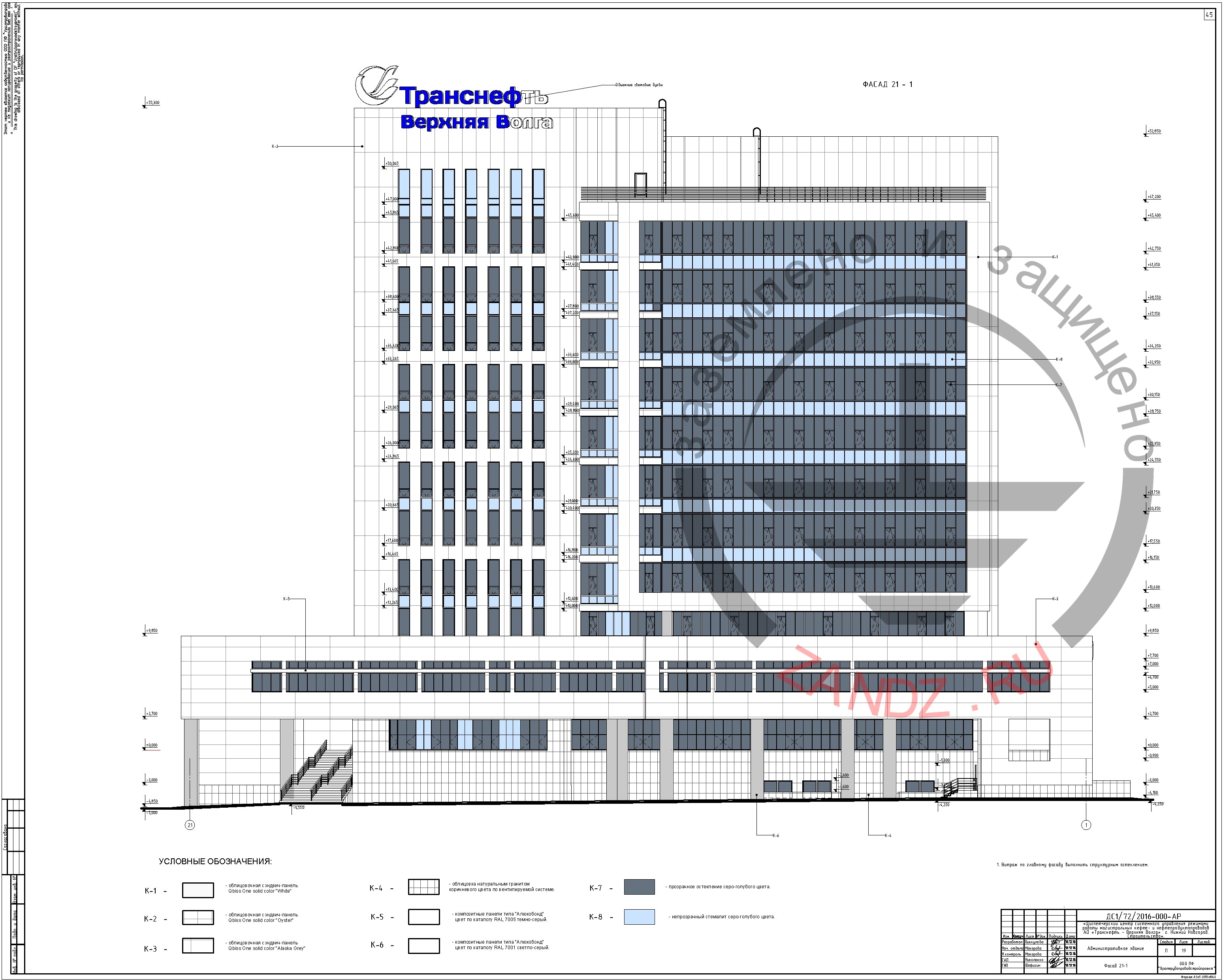
Figure 1. Facade of an administrative building
Task:
To calculate the lightning protection system for an administrative building. The protected facility is classified as a conventional facility in terms of lightning protection according to SO and to Category 3 according to RD.
Solution:
Calculations of the lightning protection are made in conformity with the following documents:
- "Electrical Installations Code" (hereinafter, EIC), EIC 7th edition.
- "Guidelines for Arrangement of Lightning Protection of Buildings, Structures, and Industrial Utilities" SO 153-34.21.122-2003 (hereinafter, SO).
- "Guidelines for Arrangement of Lightning Protection of Buildings and Structures" RD 34.21.122-87 (hereinafter, RD).
Protection of buildings against lightning strikes is provided by using lightning arresters. Lightning arrester is a device that is elevated over the protected facility through which the lightning current goes into the ground bypassing the protected facility. It consists of a lightning rod that directly accepts the discharge of a lightning , a current collector, and a grounding electrode.
Description of the external lightning protection system
A set of arrangements ensuring compliance with the lightning protection requirements is based on the following solutions:
- Lightning rods are installed:
- 6 with the height up to 7 m (1 m for securing);
- 1 with the height up to 10 m (1.5 m for securing).
- Along the roof perimeter, current collectors are laid using the copper-plated wire D = 8 mm in at least 20 meters, which are connected to an artificial grounding electrode.
- Lightning rods are also interconnected to arrange two current collectors from each lightning rod.
- Along the building perimeter, at design elevations + 21,000 and +37,000, horizontal bars made of copper-plated steel with the diameter of 8 mm are laid, which are secured to the wall using clamps GL-11703A.
- Band connection to current collectors is made using clamps GL-11551А.
- The main conductor cables are mounted (installation step 0.6-1 m):
- on a flat roof using clamps GL-11711;
- on the walls using clamps GL-11703A.
- Connection and branching of main conductors are usually made using clamps GL-11551А.
A set of measures to ensure the requirements for the grounding arrangement is based on the following solutions:
- A horizontal circuit is laid around the building. The circuit is made of corrosion-resistant copper-plated steel bar 4 x 30 mm, depth 0.5 m, the distance to the building wall at least 1 m.
- The horizontal electrodes are connected to each other using connection terminal ZZ-005-064.
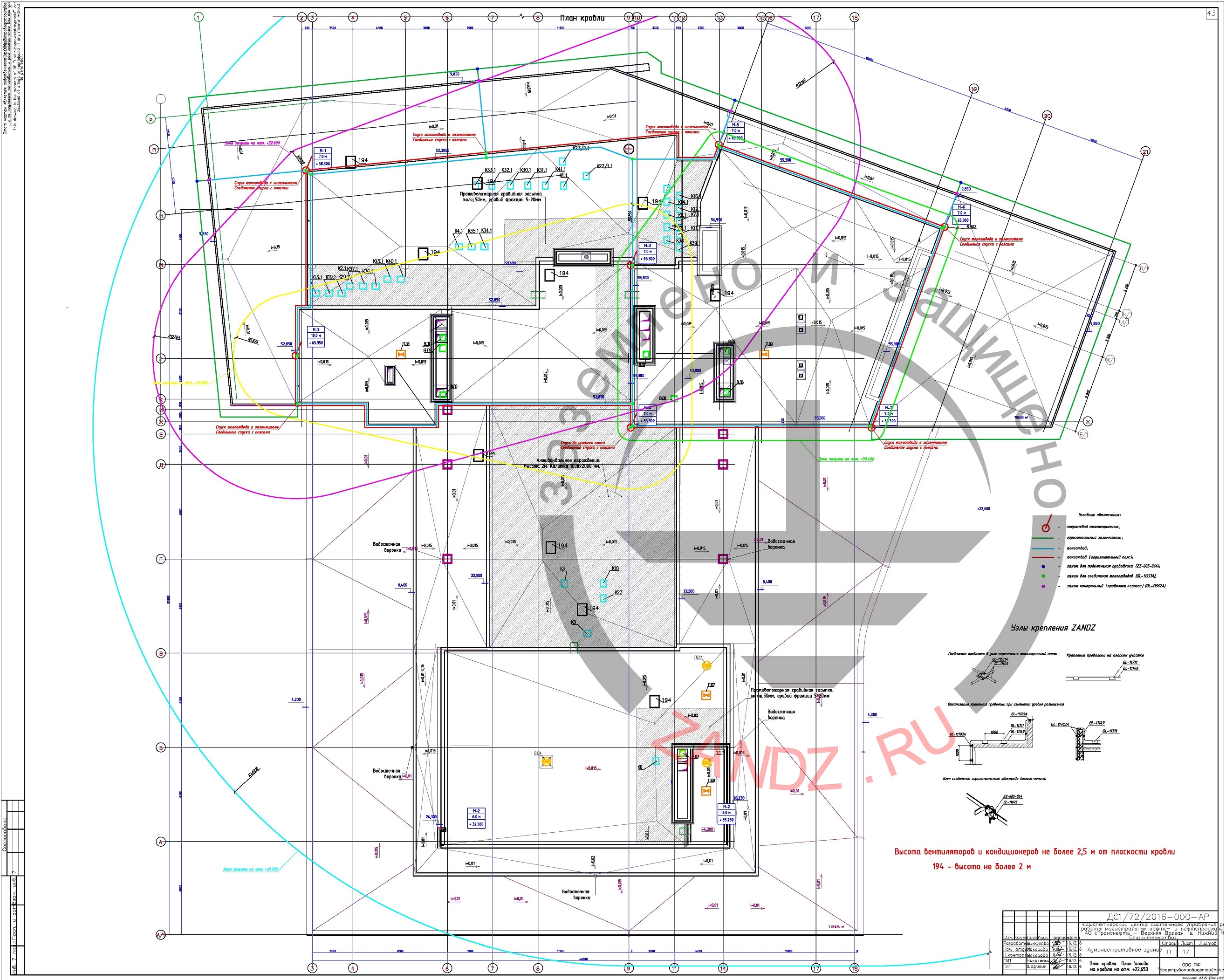
Figure 2. Lightning protection and grounding elements layout plan
Protection reliability calculation
The density of lighting discharges into the ground is 4 strikes/sq. km per year;
To calculate the lightning protection from the ground, a zero level is taken at -4,000.
The results of the calculation of the lightning protection performed using the software developed by the OJSC "Krzhizhanovsky Energy Institute" (OJSC ENIN) are provided in Table 1.
Table 1. Results of lightning protection calculations
|
№ |
Facility |
Lightning rod height, m |
Protection reliability |
Number of strikes into the facility, year - 1 |
Number of blowouts into the facility, year - 1 |
|
Period of strikes, year |
Period of blowouts, year |
||||
|
1 |
Administrative building |
7 and 10 m |
0,926 |
0,65 |
0,048 |
|
once per 2 years |
once per 21 years |
The list of necessary materials is given in Table 2.


The listed equipment provides reliable protection from lightnings which has been proved by the calculations made in the software.
Internal lightning protection (SDP)
To protect the equipment and electrical utilities inside the building, we recommend employing a set of measures which allows preventing dangerous overvoltage.
1. Protection in a main distribution panel
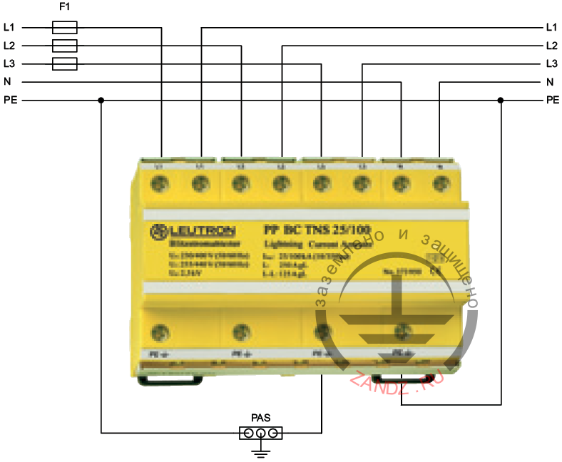
The main distribution panel contains the surge protection device SDP Class I+II+III PP BCB TNS 25/100 selected according to a three-phase input to the building and power system TN-C-S or TN-S.
The connection is made consecutively (V connection). We recommend using the fuse F1 (see the diagram) without a delay, with the rate of up to 125 A.
If an input breaker (or protective fuses instead of it) calculated according to the power grid load and its rated value is less than 125 A, the installation of additional fuses F1 is not required.
The SDP connection scheme is shown in the Figure 3.
Figure 3. Class 1+2+3 SPD connection scheme
2. Protection in floor/secondary distribution panels
With the length of the line between main and floor panels exceeding 10 m, Class II SDP EP C TNS 275are installed in the floor distribution panels.
The connection is made consecutively (V connection). We recommend using the fuse F1 (see the diagram) without a delay, with the rate of up to 125 A.
If an input breaker (or protective fuses instead of it) calculated according to the power grid load and its rated value is less than 125 A, the installation of additional fuses F1 is not required.
The SDP connection scheme is shown in the Figure 4.

Figure 4. Class 2 SDP connection scheme
Table 2. List of required materials for internal lightning protection
|
№ |
Photo |
Part number |
Name |
Q-ty, pcs. |
|
1.
|
 |
LE-373-960 |
1 |
|
| 2. |  |
LE-381-178 | LEUTRON Surge protector (SDP) EP C TNS 275 | According to the number of floor distribution panels |
Without specified measures, the facility lightning protection is incomplete, since only the use of protective devices allows reducing the grid surge to the safe level for the protected equipment.
Do you have any questions related to the lightning protection and grounding system for an administrative building?
Please, contact the ZANDZ Technical Center!
See also: