The ZANDZ Technical Center often receives requests for calculations of grounding arrangements with a rather low resistance of 0.25-0.5 Ohm.
Some of such calculations are related to buildings in Moscow. They have built-in transformer substations connected to the developing 20 kV grid. Special features of the grid are as follows:
- 2x increased voltage allowing more power to pass through;
- low-resistance neutral grounding, unlike 6, 10, or 35 kV grids with an isolated neutral or a neutral grounded through a high-resistance resistor or arc-suppression coil;
- the need for selective cut-off of single-phase earth faults through protective automation and reducing surge exposure times for the equipment and grid insulation, which increases the grid reliability.
These aspects are greatly detailed in an analytical article written by specialists of PAO Rosseti and AO Unified Energy Company titled "Regulation of conditions to ensure electrical safety in urban 10-20 kV distribution power grids with a low-resistance neutral grounding".
The problem is in that, essentially, the 20 kV grid is an average voltage grid though with a different configuration of transformer windings. And if, in 10, 35 kV grids, with an insulated neutral wire or a neutral wire connected through an arc-suppression coil, or a high-resistance resistor, the grounding currents are rather low, then, in case of arrangement of a low-Ohmic resistance of the neutral in the 20 kV grid, currents flowing through the grounding arrangement are about 1,000-2,000 A, which makes it possible to arrange the selective operation of automation to cut off the single phase-to-ground fault protection.
When you try to calculate the grounding arrangement resistance using the formula provided in item 1.7.96 of the EIC for the grids with low grounding currents:
R≤250/Isc
where Isc is the estimated grounding current, A;
you obtain R=0,125-0,25 Ohm - very low resistances, which are very difficult to obtain practically.
If you follow requirements related to grounding arrangements in the grids with efficiently grounded neutral and make calculations (the grounding arrangement conformance to its resistance, or touch voltage, or limitations of the voltage at the grounding arrangement), according to item 1.7.88 of the EIC , rather low resistances can be obtained. Therefore, item 1.7.90 of the EIC specifies a requirement to the grounding arrangement resistance of 0.5 Ohm, and the value can only be obtained, e.g. on an open-type 110 kV switchgear, but not when it is necessary to create a grounding arrangement in cluttered urban environment for a closed 20/0.4 kV transformer substation, which is also usually integrated into the building. Basically, a main criterion of low grounding arrangement resistances is the need to comply with the electrical safety in terms of the allowable touch voltage (specified in GOST 12.1.038-82), however, unfortunately, current regulatory technical documents lack methods and techniques for calculation of touch voltages with sufficient accuracy. The most relevant use of GOST R 50571.4.44-2019 is to calculate allowed voltages occurring in a high-voltage grid at the enclosure of the electrical equipment in case of its damage. However, when power supply companies issue specifications for technical connection, they set very strict requirements in terms of resistance of the grounding arrangement based on the above section in the EIC, related to the grids with insulated neutral wires.
Solution
The problem of obtaining low resistances for the grounding arrangement has several solutions:
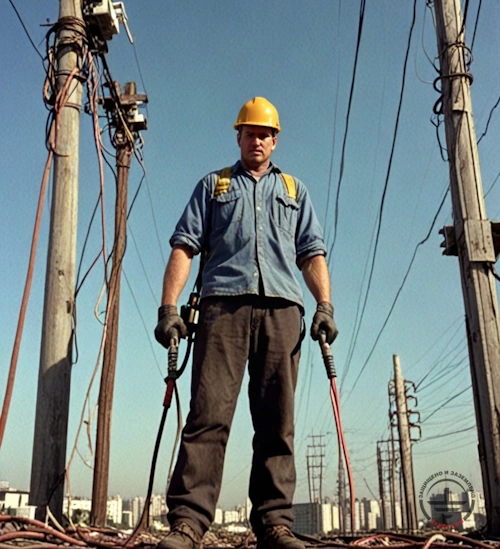
- Using electrolytic grounding sets:
1.1. High efficiency with lower dimensions of the grounding arrangement.
This is especially relevant for urban areas, in reconstructions of existing buildings, when only some limited space is available for installing the grounding arrangement, since the urban land improvement has already been made, or if the building perimeter is heavy with other utilities.
1.2. Soils have a very high electrical resistivity..
The electrolyte solution, when penetrating through the near-electrode filler to the soil surrounding the electrode, reduces its electrical resistivity thus providing a more efficient short-circuit current drain to the ground.
Installation of electrolytic grounding
- Using the grounding circuit
Commonly, newly commissioned substations in a new 20 kV grid are part of a complex construction and are integrated into rather large construction facilities, such as malls, administration centers, residential complexes consisting of several buildings and having extended grounding circuits.
2.1. Large grounding circuits also allow achieving the required resistance, especially in soils with low resistivity (clay loams, clays, etc.).
2.2. Moreover, extended grounding circuits take off the issue of voltage drops in various accidents since closely spaced buildings are connected to a single grounding arrangement.
- Using natural ground terminals
Performing activities that allow the use of building foundations and natural ground terminals:
- arranging reliable electrical connections between reinforcing cases of the reinforced concrete structures, metal frames, pile casings, etc.
- possible effects of the lightning and short-circuit current flow, which may cause intolerable mechanical loads, are taken into account.
- when making waterproofing layers, synthetic materials were not used, since, if they are employed, the building foundation cannot be used as a ground terminal of the lightning protection.
- drains are arranged from reinforced concrete products, to which the lightning protection, grounding, and equipotential bonding systems can be connected.
The above requirements must be considered at the design step and are not always suitable for reconstruction or upgrade of the existing facilities.
The drawbacks of the method may include:
- complex calculations;
- additional non-core scopes of work for the construction brigades involved in the reinforcement and concrete work;
- complex control and inspection of the obtained grounding system.
- back filling of reinforced concrete foundations is usually made with sand having a relatively high electrical resistivity.
- Using natural ground terminals along with artificial ground terminals
In case of a situation when using the above method you cannot obtain the required resistance, you can add to a grounding arrangement made of natural ground terminals either electrolytic grounding, or modular grounding and, thus, produce the expected result.
Need a design of earthing and lightning protection? Order now by contacting the ZANDZ Technical Center!
Related Articles: