(held on August 8, 2018 at 11:00 Moscow time)
The webinar is intended for: designers of lightning protection and earthing
Venue: online (you will need the Internet access on your PC)
Fee: free of charge
Duration: 60 to 90 minutes
A series of webinars titled "Electromagnetic Compatibility with Lightning", a new book of E.M. Bazelyan
The aim of the second webinar is a certain description of engineering methods for the evaluation of parameters required to determine the practical danger of electromagnetic effects. This issue has been partially examined during our webinars. In this case, we will talk about the simplest but correct calculation methods.
1080p full screen watching is recommended.
Webinar text. Page 1
Approximate reading time: 43 minutes.
Electromagnetic compatibility with lightning
ЭЛЕКТРОМАГНИТНАЯ СОВМЕСТИМОСТЬ С МОЛНИЕЙ
(Что и как рассчитывать)
Вебинар двадцать первый
Д.т.н. проф. Э.М. Базелян
АО «ЭНИН» Москва
ELECTROMAGNETIC COMPATIBILITY WITH LIGHTNING
(What and how to calculate?)
The twenty-first webinar
Dr. Sc. (Eng.), Prof. E.M. Bazelyan
«ENIN» AO, Moscow
– Dear colleagues, this is the twenty-first, milestone seminar. It is a good number but I feel uncomfortable. I think that at this point, the coordinator will interrupt me and read a message of a participant saying: "Mr. Professor, stop messing with our heads. The theoretical base for electrical engineering was created more than a century ago. All possible calculations were made then. We have already studied this discipline and we know all of these calculations. Why do you mess with our heads? Go home and relax. We will look into the subject without you. And I will not be able to reply and object to such message because it is true. The theory of electrical engineering was completed and we cannot think of anything else in it. I have tried to think of how to justify this seminar for several days and I have come up with two things. The first thing is: unfortunately, our memory is kinky, and, without our permission, it discards everything that has not been used for some time. The computer reminds us when unused icons are present on the screen, but our memory does not. It just discards everything and forgets about it. And the problem of not using all of these is associated with the following aspect. There is a Gosstandard company. Gosstandard creates GOSTs. These GOSTs contain the appendices with many recommendations such as "use this way", "take this value", "use this number", and they provide everything ready for use and you have nothing else to do. And because we have such GOSTs, our memory deals with electrical engineering this way.
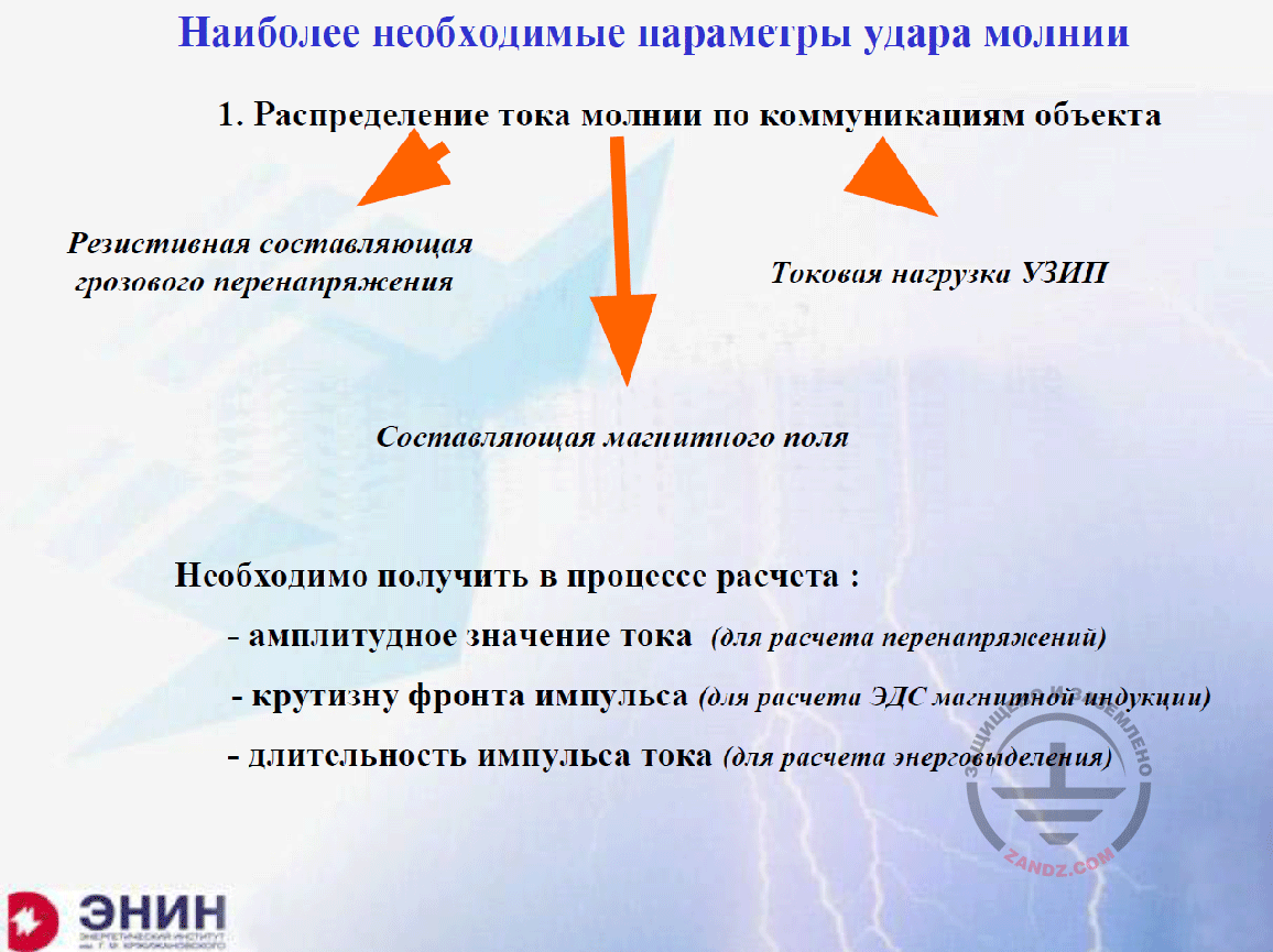
Essential parameters of the lightning strike
Наиболее необходимые параметры удара молнии
1. Распределение тока молнии по коммуникациям объекта
Резистивная составляющая грозового перенапряжения
Токовая нагрузка УЗИП
Составляющая магнитного поля
Необходимо получить в процессе расчета:
- амплитудное значение тока (для расчета перенапряжений)
- крутизну фронта импульса (для расчета ЭДС магнитной индукции)
- длительность импульса тока (для расчета энерговыделения)
Essential parameters of the lightning strike
1. Distribution of the lightning current among the facility utilities
Resistive component of a storm surge
Current load on the SDPs
Component of a magnetic field
During the calculation process, we have to obtain:
- amplitude current value (to calculate surges)
- pulse front steepness (to calculate electromotive force of magnetic induction)
- duration of current pulse (to calculate energy emission)
And I will try to prove that I have got such right to some extent. What do I want to begin with? Needless to say that with the current calculations. There is nothing else in the electrical engineering, and the lightning also has nothing like this. I need to know the lightning current distribution among the utilities of a facility it struck. What do we need it for? In the first place, it is a resistive component of the induced surge. If you multiply the current by the earthing resistance, you will receive the resistive component of the interference that acts upon the insulation of all circuits relative to the earth. And for this purpose, I need to know the lightning current and primarily its amplitude. In the second place, it is an increase rate of this current, and the duration of its front. I need this value to calculate the electromotive force of magnetic induction. A major component we have to struggle with when solving the electromagnetic compatibility issue. And in the third place, I need to know full duration of the current pulse because it is required to calculate the energy that is released in the electrical circuit and got into the SDP to be installed in the electrical circuit. This issue will be discussed in our large and serious seminar on October 5. It means that I need to know how the lightning current is distributed among the facility utilities and I need to know the amplitude, the front duration, and the full pulse duration. That is all I need to know.
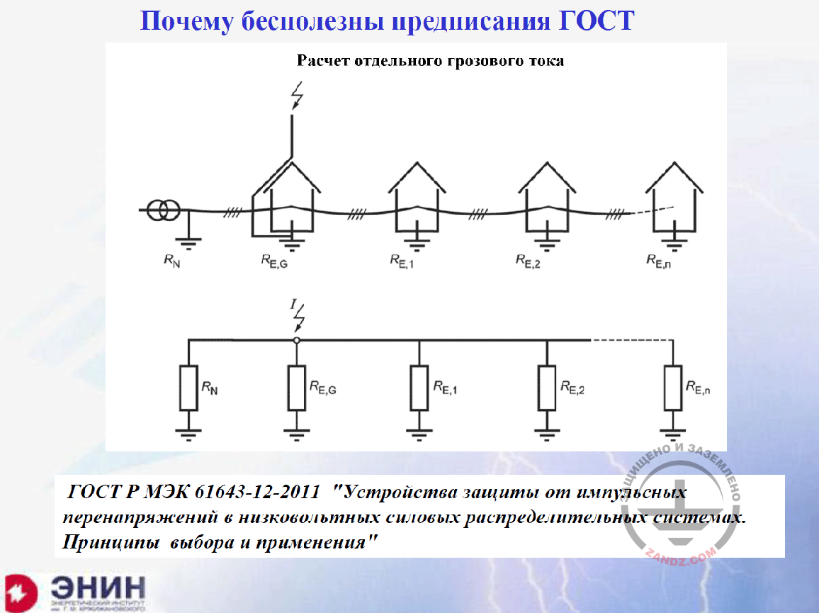
Why are the GOST directions useless?
Почему бесполезны предписания ГОСТ?
Расчет отдельного грозового тока
ГОСТ Р МЭК 61643-12-2011 «Устройства защиты от импульсных перенапряжений в низковольтных силовых распределительных системах. Принципы выбора и применения»
Why are the GOST directions useless?
Calculation of a separate storm current
GOST R IEC 61643-12-2011 «Surge protective devices connected to low-voltage power distribution systems. Selection and application principles»
Then, I want to show how the standards in Russia, which are called GOST R standards, handle this. It means that this Russian Standard has translated one of the IEC standards into Russian and published under its own name. The picture you can see now is an accurate copy of the picture contained in the standard provided under the picture. And this standard is called "Surge protective devices connected to low-voltage power distribution systems. Selection and application principles". And the picture is provided, according to which you must calculate the lightning current distribution after the lightning strike into the facility. Look at the replacement scheme. The replacement scheme consists of the current source and the paralleled earthing resistances of all buildings powered from this line. That is all. There is nothing except for the earthing resistance. What does it mean? What is it? Have not people heard of such term as inductivity?
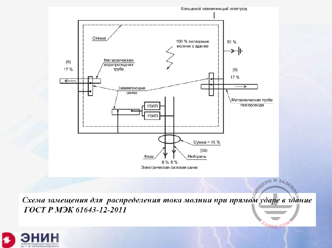
Replacement scheme for the lightning current distribution
Кольцевой заземляющий электрод
Стенка
Металлическая водопроводная труба
Заземляющие шины
Фаза
УЗИП
Электрическая силовая шина
Нейтраль
Сумма
100% попадание молнии в здание
Металлическая труба газопровода
Ring earthing electrode
Wall
Metal water supply pipe
Earthing buses
Phase
SDP
Electrical power bus
Neutral wire
Sum
100% lightning strike into the building
Metal pipe of a gas pipeline
Probably such scheme is an accident? Not even close. I can find a better scheme from another appendix of this GOST. Look at the scheme. It shows how the lightning current is distributed among the building utilities, if the lightning strikes this building. We do not need to know anything. 50% of current goes to the earthing device of the facility. It does not matter to what earthing device it goes; it is 50% anyway. And the second half, i.e. another 50%, are distributed equally among the underground and air utilities of the facility. 17% go into the water supply system, 17% go to the gas pipeline, and 16% go to the power line. That is it. You do not need to calculate anything. This is an absurd. And you just cannot think of the reason for this absurd.
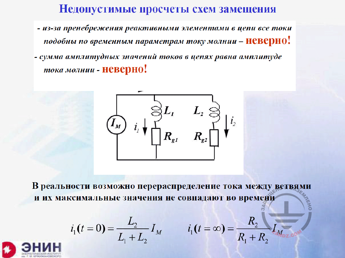
Unacceptable mistakes of replacement schemes
Недопустимые просчеты схем замещения
- из-за пренебрежения реактивными элементами в цепи все токи подобны по временным параметрам току молнии – неверно!
- сумма амплитудных значений токов в цепях равна амплитуда тока молнии – неверно!
В реальности возможно перераспределение тока между ветвями и их максимальные значения не совпадают во времени
Unacceptable mistakes of replacement schemes
- due to ignoring the reactive elements in circuits, all currents are similar to the lightning current in terms of time parameters — incorrect!
- sum of amplitude values of the currents in the circuit is equal to the lightning current amplitude — incorrect!
In real life, current re-distribution among the branches is possible, and their maximum values do not match in time
Let's see what stupid things have been introduced into the state standard. You need to understand that this is a state standard, that is why I am really confused about that. Let's see. If the inductances are not considered but we only have got active resistances, it means that, in each resistance, the current will flow having a shape similar to that of the lightning current. This is wrong. Actually, the shape of the lightning current pulse changes due to the reactive resistances. And this change is very important for choosing the SDP. But this is not taken into consideration. Let's proceed further. Due to the fact that the shapes of the current pulses match, and the current peaks coincide, the sum of currents in all circuit elements should be equal to the lightning current. This is even more incorrect because these peaks may be shifted in time, and the sums of these peaks may be several times more than the current of the lightning that struck the structure. In other words, the current, due to the reactive resistances, may flow from one element to another, and such peaks occur: one of them in 10 mcs, and another one, for example, in 50 mcs, then we cannot talk about their sum. How can we approach this solution? Here, I have drawn such a replacement scheme. Lightning is the current source, and two inductances are represented by two sections of a line. One of these sections goes to the facility, while the other section of this line goes to the substation that powers up this facility, and it means that the earthing resistance of the substation and the facility exists. Now, such replacement scheme must be calculated. A teacher that held classes for theoretical bases of electrical engineering, used to say: "A good engineer must know the electrical engineering, but a very good engineer must be a little lazy so that not to hurry up in using calculations it has been taught". Let's not hurry up with these calculations. Let's look at this scheme through the eyes of a person who knows physics. There are commutation laws. According to them, the current in the circuit having an inductance cannot change immediately because such immediate change in the current would have provided a very significant voltage drop for inductance. And for this reason, in the first time, the current will distribute inversely to the inductance values in a zero time point. It means that the current that flows along circuit No. 1, will be defined by the ratio of inductance of the second circuit to the sum of inductances. Now imagine that inductance L2 is about 10 times more than inductance L1; it means that 90% of the current in the first time point will get into circuit No. 1 the way it is shown in this formula. And after some time, in a steady operation mode, the inductances do not have any values any more, and the current will be distributed inversely to the resistance values. Now imagine that the second resistance is 10 times more than the first one. And then 90% of the current will go from circuit 1 to circuit 2, and we obtain two peaks, 90% of the current each, and, in total, these two peaks are 1.8 times more than the current provided by the lightning. It will first destroy one circuit, and then the other circuit. This enormous mistake was made first in the IEC standard, and after that it was adopted in the Russian standard.
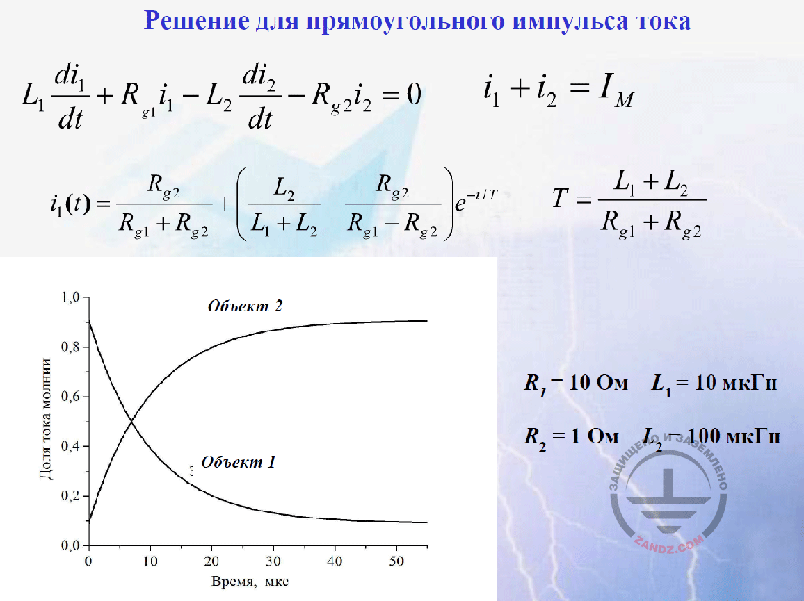
Solution for a rectangular current pulse
Решение для прямоугольного импульса тока
Доля тока молнии
Время, мкс
Объект 2
Объект 1
Ом
мкГн
Solution for a rectangular current pulse
Fraction of the lightning current
Time, mcs
Facility 2
Facility 1
Ohm
mcG
Now, after I have said this, let's look at how we may perform calculations. The equations shown here correspond to the Kirhgoff's law. They are provided in the form they are shown here. And the sum of two currents is the lightning current. Let's solve this problem for the rectangular pulse of the lightning current. I say "let's solve" because, in any reference guide, in any student's book, you may find the solution provided herein. It can be found anywhere, even in the simple textbook for the electrical engineering fundamentals. Look at it. The only equation term that varies in time is an exponent. It has got a time constant that is equal to the sum of inductance divided by the sum of resistance. Now look at what we obtain in this case. In the zero time point, the exponent is equal to 1, and L2/(L1+L2) remains of the sum of these fractions. This is what we have written on the basis of the commutation laws. And in a large time point, the exponent will drop to almost a zero, and the term of the resistances ratio will remain. I plot a graph using this formula. Look. First, one facility is loaded up to 90%, and then, in about 40 mcs, all current goes to the second facility. This is what the solution yields. And the person who follows my words, will say: "What do you solve? You have obtained the solution for the rectangular current pulse. This technical task has got a meaning for the rectangular current pulse, but in practice, the current is not rectangular." Indeed, in practice, the current is not rectangular. Now, after I have said all of this, let's see how we can make calculations. The equations shown here correspond to the Kirhgoff's law. They are provided in the form they are shown here. And the sum of two currents is the lightning current. Let's solve this problem for the rectangular pulse of the lightning current. I say "let's solve" because, in any reference guide, in any student's book, you may find the solution provided herein. It can be found anywhere, even in the simple textbook for the electrical engineering fundamentals. Look at it. The only equation term that varies in time is an exponent. It has a time constant that is equal to the sum of inductance divided by the sum of resistance. Now look at what we obtain in this case. In the zero time point, the exponent is equal to 1, and L2/(L1+L2) remains of the sum of these fractions. This is what we have written on the basis of the commutation laws. And in a large time point, the exponent will drop to almost a zero, and the term of the resistances ratio will remain. I plot a graph using this formula. Look. First, one facility is loaded up to 90%, and then, in about 40 mcs, all current goes to the second facility.
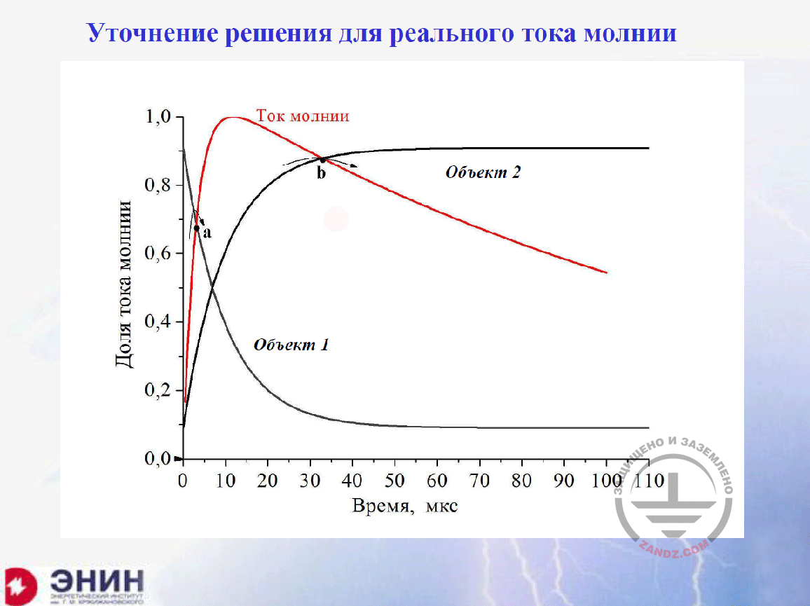
Refined solution for the real lightning current
Уточнение решения для реального тока молнии
Доля тока молнии
Ток молнии
Объект 2
Объект 1
Время, мкс
Refined solution for the real lightning current
Fraction of the lightning current
Lightning current
Facility 2
Facility 1
Time, mcs
Now, I will show you the approximate shape of the lightning current pulse. Can you see it? Its front for the first component of the lightning current is about 10 mcs, and the tail drops to about 100 mcs, i.e. to the half of the amplitude. And indeed, the task should be solved for this pulse. And if you are familiar with computational solutions on PC, you can easily calculate it. Obtain this value using any software, e.g., using MatLab. But now I want to show you that you do not need to look for and develop programs to obtain it. We have generated two curves for the rectangular current pulse. The current curve in facility 1 and the current curve in facility 2. The red curve is the pulse we have to work with. It is clear that the current cannot be more than the lightning current. And surely, you should take the red piece instead of it. And you have to take another red piece instead of it and delete the upper, beginning portion. If I do that graphically; you can see the result.
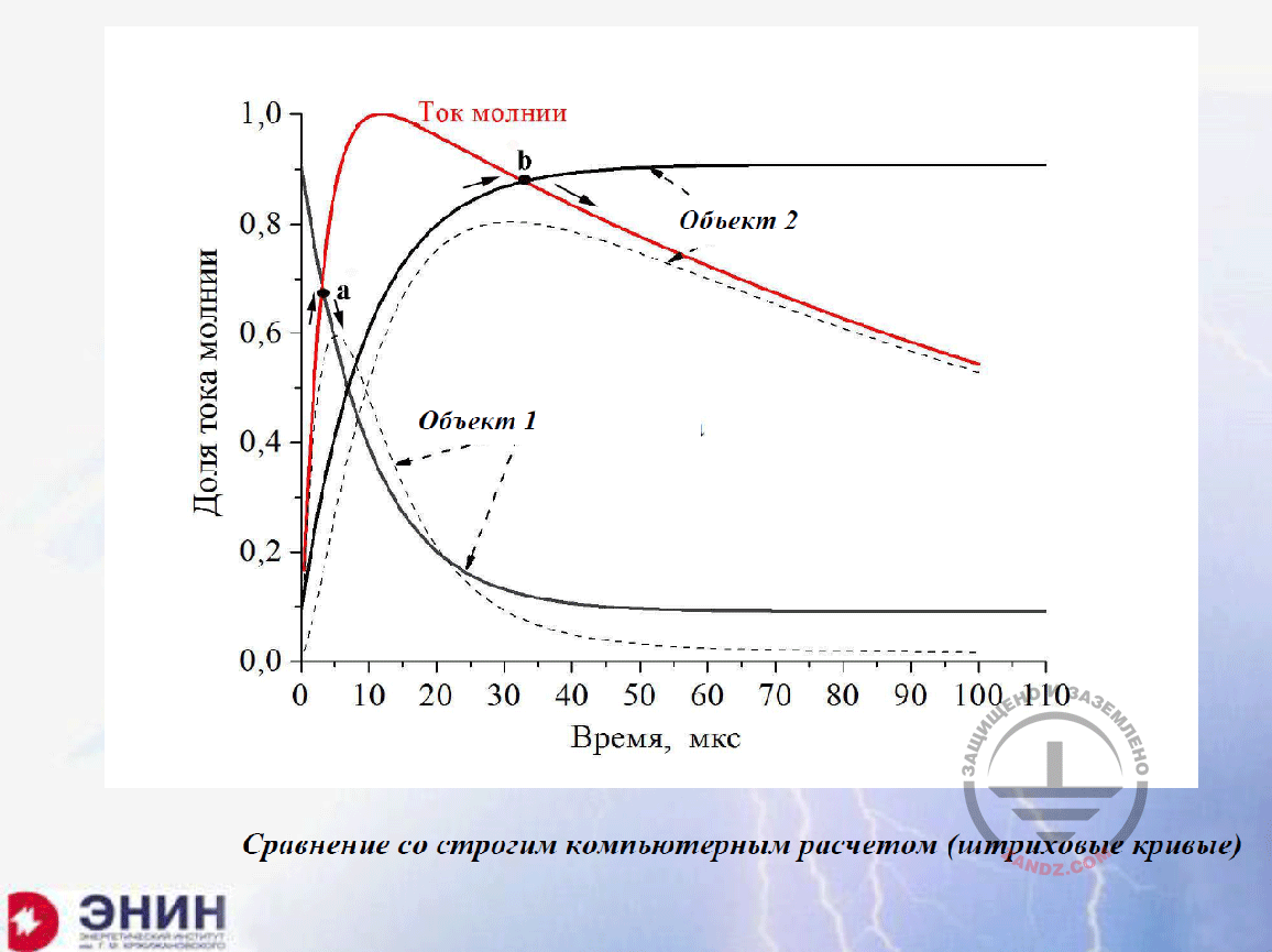
Comparing with the strict computer calculation (dashed curves)
Ток молнии
Объект 2
Объект 1
Доля тока молнии
Время, мкс
Сравнение со строгим компьютерным расчетом (штриховые кривые)
Lightning current
Facility 2
Facility 1
Fraction of lightning current
Time, mcs
Comparing with the strict computer calculation (dashed curves)
Then I will have a dotted line, the first pulse current and the second pulse current. This is what the correct clear computer solution would have provided. And now I follow the curve I have generated. These are the first pulse instead of the dotted line and the second pulse instead of the dotted line. The accurate solution differs from my solution within 10–15%. This error is acceptable in the engineering calculations. You do not have to do anything else. You only need to use the simple knowledge provided in any reference guide. This is the first point I wanted to note. Look at the pulses we have obtained. They have nothing in common with the actual lightning current pulse. And the sum of the amplitude values exceeds the lightning current significantly.
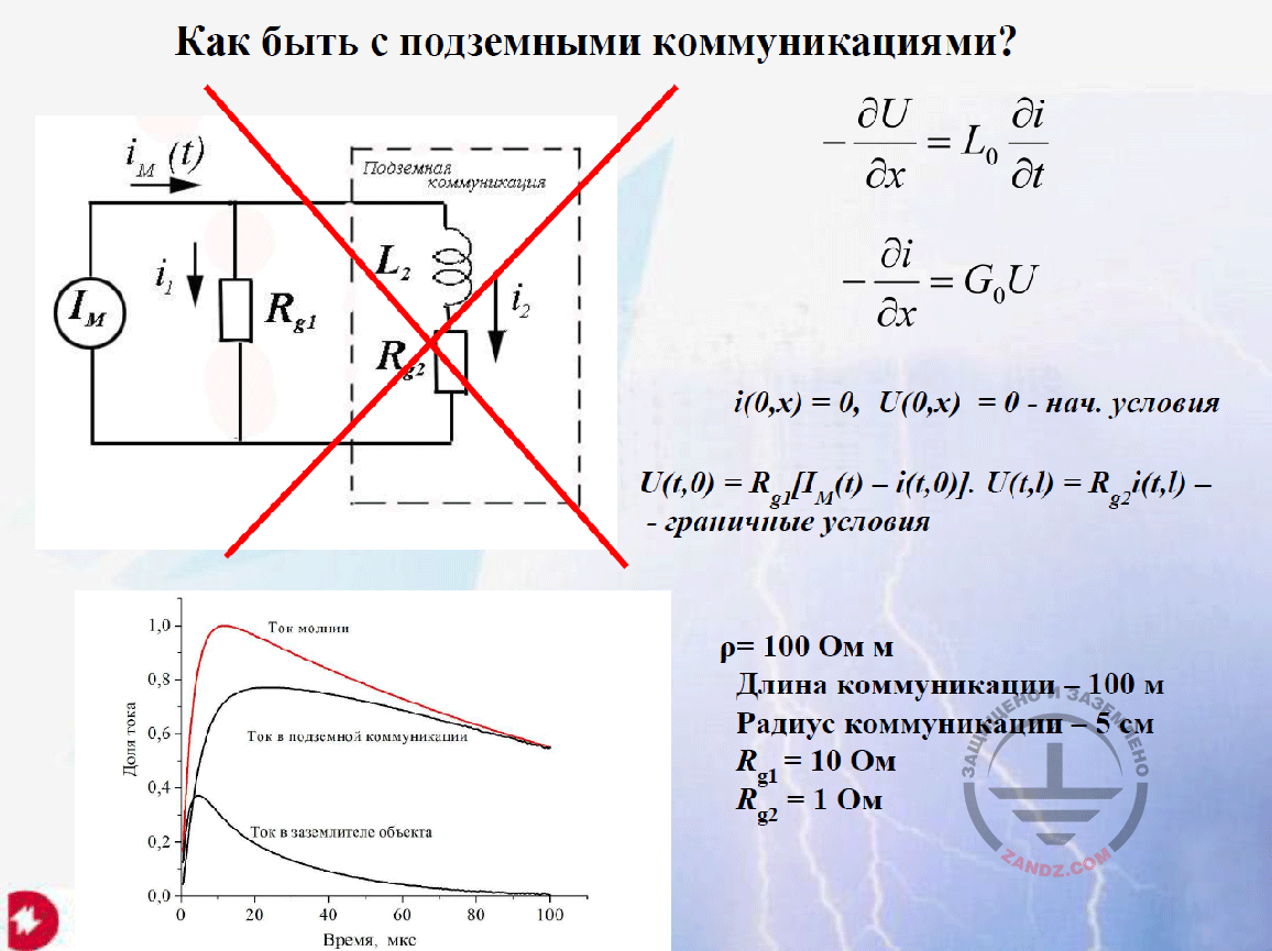
How to deal with the underground utilities?
Как быть с подземными коммуникациями?
Нач. условия
Граничные условия
Ом м
Длина коммуникации – 100 м
Радиус коммуникации – 5 см
Подземная коммуникация
How to deal with the underground utilities?
Initial conditions
Boundary conditions
Ohm m
Utility length — 100 m
Utility radius — 5 cm
Underground utilities
And there is a task of a slightly different type. It is like this. Any building has got underground utilities. For these utilities, GOST recommends to consider that they receive 17% of the lightning current. Now I want to make calculations for this underground utility. How can we do that?
– Eduard Meerovich, may I interrupt you? We have received several questions in the chat. But I think that we can answer only one of them right now. The remaining questions may be answered at the end of the webinar. Let me read it. Shamil Nizaev asks: "The previous information was a bit unclear (the actual lightning current and its distribution among the utilities are shown by a dashed line). What (excellent) result has E.M. Bazelyan obtained?"
– I will turn back to this slide "Comparing with the strict computer calculation". Look at what I have obtained. The dotted line I am showing now (the bottom curve) is the current in the first facility. And this (upper) dotted line is the current in the second facility in the accurate computer solution. If I plot a curve, I need to follow first the red curve and then turn at point a to the black curve. And then, it differs from my dotted line for only about 10%. Now, in the second facility, I follow first the black curve to point b, and then go to the lower, red curve. And the difference between accurate and my solutions is less than 10%. This is what I obtain using this approach. It means that I consider the actual shape of the lightning current using only a graphical representation. And it looks good. The second question?
– The second question is from Alexey: "Regarding the curves. The amplitude values are different. According to the standard, you use the percentage of the calculated lightning current. And in reality, it is more".
– I do not understand the question. He should clarify it.
– Alexey wrote that this is not a question but a comment. Does Alexey want us to answer his comment? It was a comment to the Shamil's question. I believe that the next questions can wait until the end of the webinar.
Next page >>
slides from 10 to 19
Related Articles:
 Lightning Protection of Large Territories: Parks, Grounds, Plant Territories. Page 1
 Lightning Protection of Large Territories: Parks, Grounds, Plant Territories. Page 2
 Lightning Protection of Large Territories: Parks, Grounds, Plant Territories. Page 3