The eleventh event of "Earthing and Lightning Protection: Design Issues and Problems" series
(video lecture was held on December 8, 2015)
1080p full screen watching is recommended
Ten previous webinars with professor E. M. Bazelyan helped the participants to solve their problems in designing earthing and lightning protection. However, even ten webinars are not enough to answer all existing questions. To do this, we gathered questions from the designers into a single list and offered the professor to answer them. Watch the video record of the lecture!
The questions that have been answered by the professor:
- How to make two independent earthing circuits if the area is limited (20 x 20 m)?
- A common earthing circuit is made for lightning protection and protective earthing, and the lightning strikes the lightning arrester. Will the lightning current go to the earthing bus through the circuit? What can it lead to? How can SDPs help in this case?
- According to item 36 of the Guidelines for Designing Healthcare Institutions (to SNiP 2.08.02-89), to provide functional earthing for the medical equipment (X-ray machine, etc.), a standalone earthing device is required. How to ensure the distance of 15 meters?
- How to design the lightning protection for the structure when the gas pipeline is located nearby (in 10 meters)?
- Are the decorative lightning arresters efficient?
- How to make the lightning protection for an open area wherein a lifting crane operates?
- Can we use a foundation based on crew piles as an earthing device?
- What problems are associated with the electrode installation at the distance of less than 1 meter from the foundation as it is specified in SO 153-34, item 3.2.3.2?
- What document allows using steel for earthing the high-voltage units?
- How is the onshore gas pipeline protected against lightnings? Should we install a standalone lightning arrester near the gas pipeline tap?
Webinar text. Page 1
Approximate reading time: 34 minutes.
Specialists' answers to the questions
ОТВЕТЫ НА ВОПРОСЫ СПЕЦИАЛИСТОВ
Серия первая
Проф. Э.М. Базелян
ОАО «ЭНИН» Москва
SPECIALISTS’ ANSWERS TO THE QUESTIONS
First series
Prof. E.M. Bazelyan
OAO “ENIN” Moscow
– Good afternoon, dear colleagues. We have already seen each other during 10 seminars. However, not all questions could be answered. Some questions have been left unanswered. Now we will gather such questions and try to provide particular answers to each question separately. I will begin with the first one.
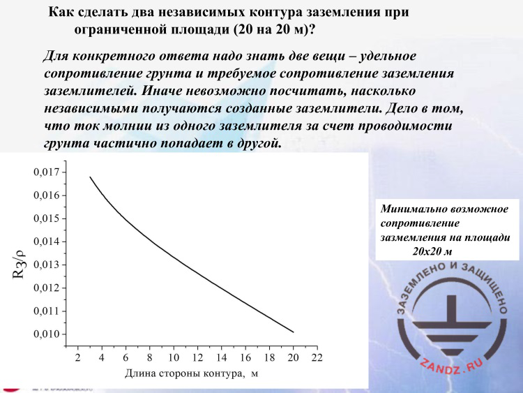
How to make two independent earthing circuits if the area is limited (20 x 20 m)?
Как сделать два независимых контура заземления при ограниченной площади (20 на 20 м)?
Для конкретного ответа надо знать две вещи – удельное сопротивление грунта и требуемое сопротивление заземления заземлителей.
Иначе невозможно посчитать, насколько независимыми получаются созданные заземлители.
Дело в том, что ток молнии из одного заземлителя за счет проводимости грунта частично попадает в другой.
Длина стороны контура, м
Минимально возможное сопротивление заземления на площади 20х20 м
How to make two independent earthing circuits if the area is limited (20 x 20 m)?
To provide a particular answer, you need to know two things: the soil resistivity and the required earthing resistance of the earthing devices.
Otherwise, it is impossible to determine how independent obtained earthing devices are.
The point is that the lightning current partially goes from one earthing device to the other device due to the soil conductivity.
Length of the circuit side, m
Minimum possible earthing resistance in the area of 20 x 20 m
– How to make two independent earthing circuits if the area is limited (20x20 m)? I do not know how to do that because I do not know at least two parameters. The first parameter is: what resistance values should be obtained? A person who asked this question did not respond to it. And the second is: where is the facility located where such earthing should be made? What is the soil resistivity there? No answer. But I do not want to leave such an important question without any answer. That is what I want to say. If your area is limited, you can achieve the resistance that is not less than a particular value. Even if you fill the entire area with metal, you will not be able to obtain any resistance. You will obtain only the value that is possible for this soil. And such dependence is plotted in the slide. I have filled the entire surface of 20 x 20 meters with metal to the depth that is shown on x-axis. And y-axis provides the earthing resistance we obtain. And to provide the suitability of this function, this value is divided by the soil resistivity. If I fill the entire space with the rods of five meters long, then I will have a value of 0.016 which yields the earthing resistance if I multiply this value by the soil resistivity. For example, it will be 1.6 Ohm, which is a good resistance, if you have a resistivity of 100 Ohm m; but if it is 1,000 Ohm m, then it will be 16 Ohm. And if it is 2,000 Ohm m, then it will be 32 Ohm. And this way we cannot make any earthing resistance in the area described in the question. And if you begin increasing the rod depth, then naturally, the earthing resistance will decrease. However, it does not decrease this rapidly. For example, if the rods are 20 meters deep, and your cannot install larger rods in the soil, you have a calculated a value of 0.1, and it means 1 Ohm with the soil resistivity of 100 Ohm m, but with the resistivity of 1,000 Ohm m, we will obtain 10 Ohm here. It means that you cannot obtain any earthing resistance in the limited area. This is the first point.
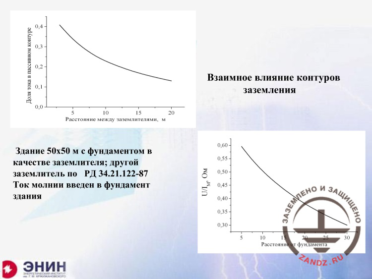
Mutual influence of earthing circuits
Доля тока в пассивном контуре
Расстояние между заземлителями, м
Взаимное влияние контуров заземления
Здание 50х50 м с фундаментом в качестве заземлителя; другой заземлитель по РД 34.21.122-87
Ток молнии введен в фундамент здания
Расстояние от фундамента
Current fraction in the passive circuit
Distance between the earthing devices, m
Mutual influence of earthing circuits
Building of 50 x 50 m with the foundation used as an earthing device; another earthing device according to RD 34.21.122-87
Lightning current is introduced into the building’s foundation
Distance from the foundation
– I am showing the following situation to you. I have a distance between the earthing devices. So, the maximum distance of 20 meters that may be obtained in this area, and you cannot make it less. And it is seen here that only at least 15% of the lightning current will get into the earthing device you consider to be isolated. And the next graph shows what surges appear in this case. If we use the distance of 20 meters, then the surge divided by the current will be 0.4. It means that with the calculation current of 100 kA for the third lightning protection level, your surge at this earthing device will be 40 kV instead of 0. It is a rather high value we have to deal with. And you cannot make it any lower at the distance of 20 meters. What is next? What else can you do? You can do the following. You are permitted to hide it deep in the earth. You may go deep for 20 m, 30 m, and even more. But in real-life conditions, you will not be able to go deeper than for 20 or 30 meters. This is because it is technologically complicated.
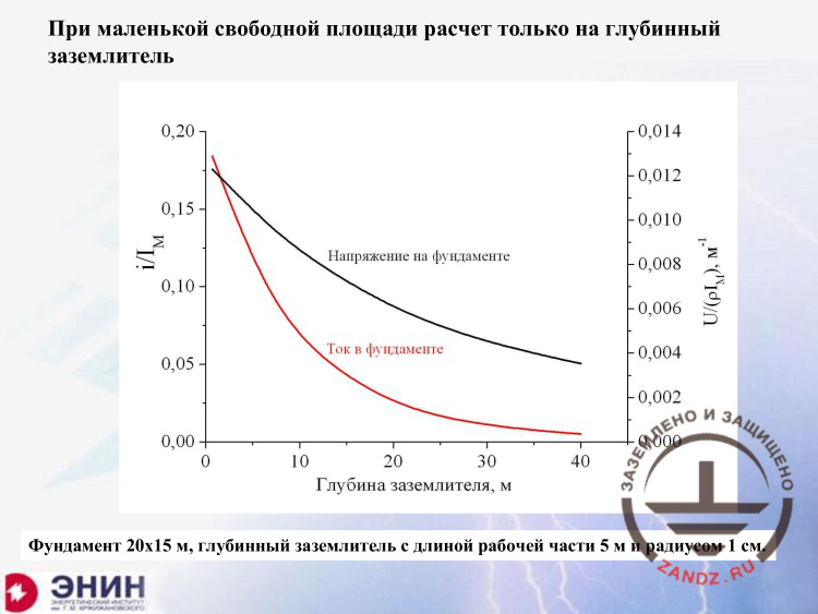
Calculation of an earth rod
Напряжение на фундаменте
Ток в фундаменте
Глубина заземлителя, м
Фундамент 20х15 м, глубинный заземлитель с длиной рабочей части 5 м и радиусом 1 см
Voltage at the foundation
Current in the foundation
Earthing rod depth, m
Foundation of 20 x 15 m, earth rod with the length of the working part of 5 m and the radius of 1 cm
– And look, if I take the depth of 20 meters, I will obtain the following thing. The current in the earthing device remains at the level of several percent. Note that this is several percent of the lightning current. It means that, for example, if it is the first lightning protection level, then several percent of the current is 200 kA. We are talking about several kiloamperes and the voltage that exists in this case. In this case it turns out that your voltage will have the value that is obtained by dividing by the soil resistivity and the lightning current. For example, if you have 1,000 Ohm m, and for Russia, it is a rather good soil, then you will obtain 6 V for each ampere of the current.
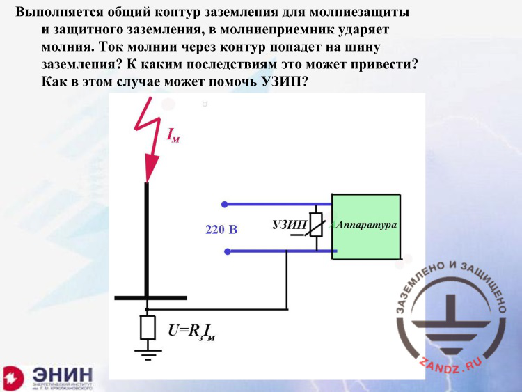
How can SDPs help?
Выполняется общий контур заземления для молниезащиты и защитного заземления, в молниеприемник ударяет молния.
Ток молнии через контур попадет на шину заземления?
К каким последствиям это можно привести?
Как в этом случае может помочь УЗИП?
УЗИП
Аппаратура
Common earthing circuits are made for the lightning protection and the protective earthing. The lightning strikes the lightning arrester.
Will lightning current flow through the circuit and get onto the earthing bus?
What consequences may it lead to?
How SDPs may help in this case?
SDP
Equipment
– Now, the second question. It is very pleasant for me because I have a particular answer to it. Moreover, if the webinar was not being recorded, I would have said: open webinar No. 3. It details what SDPs do and how they protect against surges associated with the lightning current. The question is as follows. Common earthing circuits are made for the lightning protection and the protective earthing. The lightning strikes the lightning arrester, the lightning current flows through the circuit and gets onto the earthing bus. What consequences may it lead to? How SDPs may help in this case? We have studied this question in details, but I will briefly answer it. In the slide, the lightning arrester, its earthing device, the lightning current that flows through the lightning arrester, through the earthing device of this lightning arrester that is connected to the common earthing circuit of the facility. And it means that at the earthing bus of the entire equipment, a potential is raised relative to the earth, for the value of the earthing resistance multiplied by the current. For example, if you have the lightning arrester having a very good resistance of 10 Ohm, which is, for example, rated in the "Gazprom" standard for the first level of the lightning protection, then if you multiply these 10 Ohm by the calculated lightning current of 200 kA for the first level of the lightning protection, you will obtain 2 million V. These 2 million V appear at the neutral bus of the 220 kV power source, and the second bus, a phase, is under the 200 V voltage relative to the earth, and thus the equipment that is connected to these buses is exposed to the voltage of 2 million — 220 V.
Next page >>
slides from 6 to 9
Related Articles:


 Lightning Protection of Large Territories: Parks, Grounds, Plant Territories. Page 1
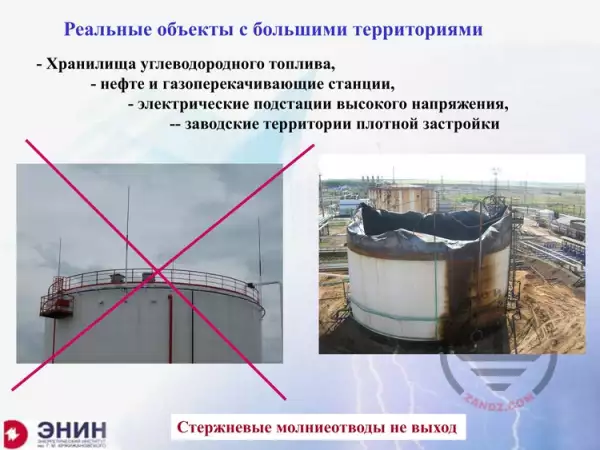 Lightning Protection of Large Territories: Parks, Grounds, Plant Territories. Page 2
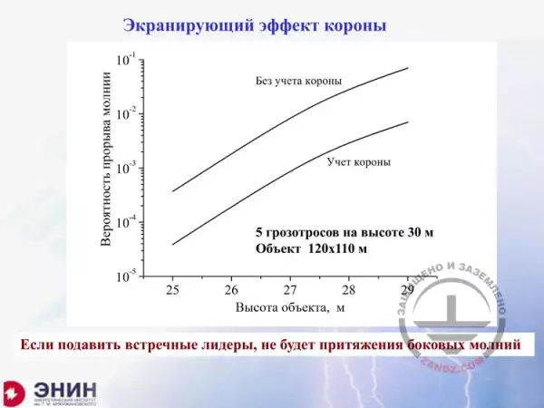 Lightning Protection of Large Territories: Parks, Grounds, Plant Territories. Page 3

