
E. M. Bazelyan, DEA, professor;
Power Engineering Institute to the name of G.M. Krzhizhanovsky , Moscow;
recognized Russian expert in the field of grounding and lightning protection.
An idea to write an article on the worst lightning protection can be a problem. The worst lightning protection is its complete absence. So, what can be said about something that is absent? But still I wanted to do that because a traditional set of problems exists in this area. It was formed during many years of design work by many specialists and these mistakes have repeated in various designs for many years. They are related to lightning rods, current collectors, and ground terminals. This traditional set pre-defines the lightning arrester of any structure.
I don't think that listing traditional mistakes will be some kind of revelation but it would be great if this "list" would even draw some attention to the points that have been known for long and even studied in details but still fit (habitually?) the 2022 design.
Lightning Rods
Lightning rods and wire lightning arresters have been used in the regulatory documents of the most technically developed countries for almost a century. This is also true for lightning protection grids. What is a grid? Physics says that this is just a repeated wire lightning arrester. Mutually perpendicular wires are spaced at several meters, 5 to 12 m according to various standards. There is nothing exceptional in repeated wire lightning arresters. The point is not about repeating wires but their small excess above the protected surface in what is called a grid. Excess of 0.1 m is considered sufficient.
I have a feedback to the GOST design for lightning protection intended for use in the CIS countries. Protection zones of wire lightning arresters do not differ from those used in well-known Instructions SO-153.34.21.122.2003. For the good of the cause, I have to boast a little bit: it was me who, by using my own PC, determined the protection zones dimensions of the wire lightning arresters for Instruction SO-153.34.21.122-2003. And now, using the same method and the same software, I am ready to evaluate the grid efficiency. Let's assume, for clarity, that a facility is 15 m high and has a flat smooth metal roof. The computer calculation results show an approximately uniform lightning distribution between the roof and the grid protecting it which takes about 50% lightnings. In other words, we cannot talk about any kind of efficient protection action of the grid since even for protection level III, reliability of 0.9 is required.
Those who wish may repeat the calculation by using the program on the ZANDZ site and provided free of charge.
A brief reference. The lightning arrester made as a grid was offered only for dielectric roofs. When it is installed on such roof, it can protect people and equipment located on the top floor of the building. With an isolation gap of a couple meters the grid seems to be pretty efficient. Anyway, it will surely be able to provide protection reliability of 0.9. Unbelievers, please, carefully readitem 2.11 of Instruction RD 34.21.122.87. A non-metal roof is mentioned there in the very first line. It is unclear who insisted on using grids for metal and reinforced concrete roofs. They are completely useless in such cases.
Using the grid for metal and reinforced concrete roofs is a very bad lightning protection.
On the contrary, a high lightning arrester is not something useless. This is impressive! The structure of 100 to 150 m high reasonably attracts the attention of newsmen from the central TV channels. The Internet knows more than one article describing ambitious and advanced decision of a designer team. However, there is no lies in here. Indeed, the high lightning arrester protects. The protection zones of the lightning arrester up to 150 m high have even been described in Instruction SO-153.34.21.122-2003. The protection radius of the lightning rod at the ground level with reliability 0.999 is equal to 60 m, and with reliability of 0.9, it is close to 170 m.
The provided figures are alarming, especially when high-reliability lightning protection is designed. Radius of 60 m is not that much for such a high lightning arrester
Magnetic field from the lightning arrester current does not differ much from the current field in the lightning channel. Therefore, the high lightning arrester should be considered as a source of strong electromagnetic fields influencing the protected object This is very dangerous if an adjacent protected object is packed with microelectronics which controls technological processes.
Current collectors
Seems like there are no particular problems with current collectors. According to the standards, the lightning current should be transported from a lightning rod to a grounding terminal via at least two current collectors. And connection between a building roof and the grounding terminal should be made via a current collector system. They are installed with a spacing of 10 to 25 m depending on the specified protection level. Instructions are very particular and cannot be interpreted ambiguously. However, sometimes confusions occur. Isolation and standalone lightning arresters add some problems. It is easier to begin with the latter. Their installation is detailed in Instruction RD 34.21.122-87 where, in particular, minimum allowable distance from the lightning arrester to the protected object is stated. Let's leave alone rating of this distance. It is important that it does not exceed several meters, with the minimum of 3 m.
And now, let's talk about current collectors. A standalone lightning arrester usually functions as a current collector due to its metal support.
However, a magnetic field of about 104 A/m is not a benefit for any advanced microelectronics.
For typical structures, electromagnetic interference does not pose any special hazard. Therefore, there will hardly be any contras against using standalone lightning arresters, especially natural ones. Adjacent higher structures and even tall trees can be used as natural lightning arresters. Do not forget that any standalone lightning arrester will be markedly higher than the one installed on the roof of a protected object with the same protection reliability. You can do it if you have too much metal.
When we are talking about an isolated lightning arrester, note that all of the above also applies to it almost to the full extent. A lightning rod of an isolated lightning arrester is installed on an isolating mast that separates it from metal structures of the protected facility. The figure shows a layout option of the isolated lightning arrester to protect the electronic unit of the antenna. It was taken from an
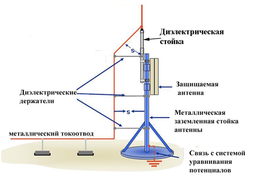
Диэлектрическая стойка - Dielectric mast
Диэлектрический держатели - Dielectric holders
Металлический токоотвод - Metal current collector
Защищаемая антенна - Protected antenna
Металлическая заземленная стойка антенны - Grounded metal antenna support
Связь с системой уравнивания потенциалов - Coupling with the potential equalization system
ad demonstrating the advantages of the system. They can actually be seen here. The lightning current is diverted from the electronic unit to the distance of several meters, due to which the electromagnetic interference to the electronic equipment was significantly reduced. The situation is indeed lucky. But this can hardly be implemented on the roof of a large building, especially when the lightning arrester is installed far from its edges. The current collector will be very long. It should extend from the roof edge and then go down to the ground terminal along the entire wall height. The structure will be ridiculous, and it cannot be implemented with insulated supports of a great length. The magnetic field of the lightning current inside the building will almost be the same as of a standalone lightning arrester. Most probably, the customer will not be satisfied with it. It is easier to divide the lightning current between many current collectors.
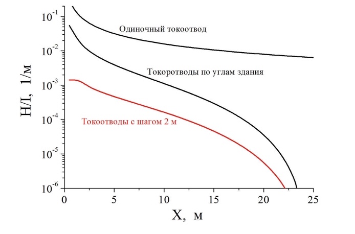
1/м - 1/m
Одиночный токоотвод - Single current collector
Токоотводы по углам здания - Current collectors at the building corners
Токоотводы с шагом 2 м - Current collectors located with the 2 m spacing
The efficiency of this activity allows evaluating the results of the computer calculation in the provided figure. They are made of the structure having the area of 50 x 50 m. Replacement of a single current collector to multiple ones installed with the 2 m spacing along the structural perimeter reduces maximum field inside of it by at least 2 orders of magnitude.
A skilled reader may note that the minimum spacing of the current collector installation is equal to ten rather than two meters. However, this is a rated spacing for specially installed current collectors. Actually, any metal parts of the structure having a continuous connection with the ground may be used. In the provided example, a metal reinforcement for glass units with the same width was proposed. By the way, here you can justify, to some extent, a lightning protection grid. It doesn't operate as a lightning arrester on the reinforced concrete roof, although it can distribute the lightning current successfully among many natural current collectors.
A single current collector of an isolated lightning arrester may be an indicator of a bad lightning protection.
Ground terminals
There is a common idea that in order to efficiently catch the lightning, the lightning arrester should have a low grounding resistance. This myth should be busted. Even in laboratory experiments, when a long spark is served as a model lightning, you cannot see how the protection radius depends on the earthing resistance. We can easily explain this. The earthing resistance reduces the voltage at the grounding rod top from where the opposite leader starts. It catches the lightning. According to the Ohm's law, the voltage reduction is defined as a production of the earthing resistance and the opposite leader current. This current is small. It is about 10 A. It means that even with the earthing resistance of 1,000 Ohm, the voltage reduction will be within 10 kV, which is a very small value compared to the voltage in the gap between the lightning leader and the ground, which is equal to several dozens MV. That's why the lightning arrester operates almost the same way with any earthing resistance. Drawbacks can be found in another aspect.
Seems like the earthing resistance should be a subject of a strict rating in the regulatory documents for lightning protection, although Instruction SO-153.34.21.122-2003 do not mention it at all, while older document RD 34.21.122-87, for some unknown reason, rates the lightning arrester design rather than the earthing resistance. Thus, irrespective of the soil resistivity, the lightning arrester can be provided with a ground terminal made as a horizontal bus with the length 10 m and three 3 m vertical grounding rod electrodes. The computer calculation of this arrangement yields an expression to calculate the earthing resistance
RG = 0,1ρ Ohm,
if soil resistivity ρ s provided in Ohm m. It turns out that everything is equally great: both earthing resistance of 10 Ohm in a good soil with ρ 100 Ohm m, and ground terminal of 500 Ohm in a rocky soil with ρ = 5,000 Ohm m. The step voltage calculation causes some serious doubts. Its results are provided in the next figure
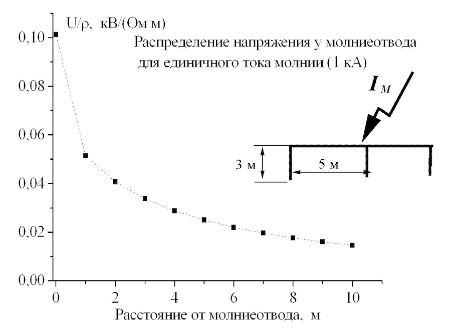
Uшаг - Ustep
Расстояние от молниеотвода, м - Distance from the lightning arrester, m
3 м - 3 m
5 м - 5 m
In a highly conductive soil, no special trouble can be predicted. Even directly at the lightning arrester, the step voltage is limited to 1,000 V. It is not good but still tolerable. But even in the soil with r = 1,000 Ohm m, a person can be at risk of exposure of about 10 kV, while at r = 5,000 Ohm m, the step voltage reaches 50 kV. It seems that this lightning arrester should be protected by a solid fencing.
This is exacerbated by the fact that city mayors adore tiles. Pavements are made using tiles instead of the asphalt. Asphalt is a good insulator. It protects from step voltage. Tiles do not allow this. They are installed with gaps filled with wet soil, and the tiles themselves are also wet in the storm. This does not provide any insulation!
Here, it is essential to tell about a dangerous level of the pulse step voltage. Unfortunately, its value is still not rated. The minimum rated voltage exposure time is equal to 0.01 s instead of 0.0001 s typical for the lightning. We have to rely on a completely formal recalculation in terms of energy. It leads to an unacceptably dangerous value of 6,000 V. Then, physiologists should say. However, even without them, every electrician will describe the contact with the 6,000 V voltage by using swear words only.
We have to say that lightning arresters with a typical ground terminal according to Instruction RD 34.21.122-87 are a bad lightning protection for regions with high-Ohmic soils.
Several words for the readers who have read until the end
There is no absolutely "bad" lightning protection. Lightning protection tools described herein have been long and successfully used in the engineering practice. The point is only in using them where they are useful. I. A. Krylov's fable about the monkey and the glasses can be mentioned here. When choosing protection means, it is critical to determine which lightning effects are the most dangerous for the protected facility. This is the only way to choose, without making mistakes, an efficient lightning protection arrangement and correctly install it. It is impossible to recommend something absolutely universal. Moreover, it is even harmful.
What should we do if the proposed design solution matches to or very similar to one of the above? There are two possible ways out: visit the nearest webinar dedicated to the subject of this article, or approach the ZANDZ Technical Center for consultation and calculation. We will be happy to help you!