
E. M. Bazelyan, DEA, professor;
Power Engineering Institute to the name of G.M. Krzhizhanovsky , Moscow;
recognized Russian expert in the field of grounding and lightning protection.
I do not really like catalogues. They are large-format and usually printed on a chalk paper, containing colorful pictures, so they somehow resemble theatrical make-up designed to hide the actor's face defects. The text in a good catalogue is correct but it does not contain all the truth. It urges us to buy and is therefore not obliged to justify the possibility of refusal to buy. In this respect, SDP catalogues are not an exception. There is something to think about here. The price of some devices is close to one hundred thousand RUB. Saving is good, especially a clever saving. This is the main purpose of the article. The consumer should clearly understand the aim of the SDP installation and know well the catalogue materials at least to distinguish advertising from actual initial data. Only this way, keeping the advertising information under control, you can choose a necessary device that can reliably and without any unreasonable cost solve your particular problem.
Even a large article can hardly provide definitive instructions to choose SDPs. The tasks solved by SDPs are too diverse as well as the conditions they should operate in. As an author, I will consider my task to be accomplished if the article helps the reader to look through any catalogue with the eyes wide open and highlight the information you really need to solve the issues while avoiding any advertising “decorations.”
Main process task of SDP
It seems to be rather particular in the times of electronic equipment. Its common use in smart technical devices makes us constantly keep in mind that microelectronic units have a low electrical strength. Many of them can be damaged by the voltage lower than 1,000 V. Time of exposure to such voltage is not particularly important. Even several fractions of a microsecond are enough. Such surges are triggered by short-time current spikes of various origins, e.g. by start-up currents of high-power motors located at a significant distance from the electronic unit.
And the lightning is what can be thought of right away. With the current up to 200 kA and growth rate up to 2 x 10¹¹ A/s, it does not have any competitors among natural events in terms of electromagnetic effects, and in engineering, we can only compare it with a high-altitude nuclear explosion. We are talking about more than the direct lightning strike into the protected facility. Even a remote lightning can be dangerous even though it is located at the distance of several hundred meters. It is clear that the remote effect occurs much more often than the direct strike. We cannot ignore this fact.
Now, let us talk about consequences. They are very diverse. A short circuit in the facility's electrical circuit may lead to fire. A powerful discharge is known to be able to cause more than damage of insulation of a power supply circuit but also explode an upstream breaker. In this case, no device can limit the short circuit current. Surely, this is the most critical situation, but the damage of electronic units can hardly be considered safe. Thus, several years ago, in storm conditions, a fire occurred in a tank farm holding liquid hydrocarbon fuel. The automated extinguishing system did not trigger and the operations control center did not receive an urgent notice on fire. The lightning being an experienced infiltrator managed to destroy all fire detectors well in advance. A similar list can be supplemented almost without any limitations. It would include damaged antenna systems, failures in aviation control units, unauthorized launches of reactive missiles, false cut-offs of operating high-voltage power lines, and substantial destruction of household electronic appliances.
All of these technical devices really need to be protected from electromagnetic field of the lightning. Although we cannot prevent electromagnetic interference, we have to think about how to create barriers in their way to the protected facility. Imagine that this is similar to how an old woman removes the TV plug from the socket in a small garden cottage and disconnects the external TV antenna cable during the storm. Then, after cutting off all ways for the interference penetration to an expensive TV, we can wait for the storm to finish.
Unfortunately, the operations control center of a regional substation or a plant control system of the automated line does not have this option. Their electronic equipment must work in any condition, including the most severe storm. Even though, during the childhood, I could experience planned electrical shutdowns in storms. Our small town located in the Moscow Region had to be immersed in full darkness during all storm hours. It is an unacceptable situation today. Protection means should be more advanced in terms of technology.
Here, it is natural to recall passive high-frequency LC filters. With the respective settings, they can significantly reduce storm interference. However, lightning parameters vary broadly in a random manner. Therefore, it is difficult to create an efficient filter. Moreover, the frequency range to fight with is partially overlapped with the frequency range of a desired signal that cannot be suppressed at all. As a result, the issue of using passive filters has become irrelevant. The focus was made on the devices capable of interfering with the protected electrical circuit only for a short time, directly during surges, and they should do that very quickly and automatically, without the interference of the operations personnel. The idea of using SDPs has emerged exactly this way.
SDP operating principle
It is very simple. You should bypass the protected equipment with a fast-acting automatic circuit breaker. In a normal operating mode, the breaker is open and does not affect the electrical circuit in any way. In case of a surge, it should trigger by shorting the circuit and thus avoid surge getting to the protected facility. It should do that for several fractions of a microsecond. This is the time required for the lightning current to grow, which causes electromagnetic interference. It is clear that no electromechanical device can be used because its triggering time is several milliseconds. We have to choose between an air-gap spark discharger and reduced-pressure gas-filled dischargers. Even semiconductor devices with a closed p-n junction are suitable. All of these are called switching-type SDPs. In fact, they provide a short circuit in the circuit, at the input of the protected equipment (Fig. 1), and thereby avoid hazardous surge getting into the equipment.
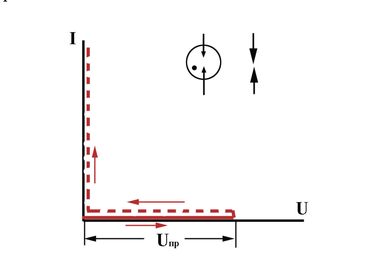
Fig. 1 Current-voltage characteristics of the arrester-based SDPs (switching-type SDPs)
The main task has been accomplished however with some difficulties. Short circuit is not an easy thing to cope with. The equipment is protected but its normal operation is disturbed. Short circuit should be removed by an upstream breaker that will completely interrupt the power supply. We cannot rule out that the SDP itself will be destroyed by the short-circuit current. Since we have to stick our (in particular, the SDP enclosure) neck out, the work can be hardly considered well organized in terms of technology.
We should search for an essentially new solution. The search direction is well known. Short circuit is a last resort. Perhaps, it is not necessary to make it in every situation. Probably, it is worth using a special resistor at the input of the protected equipment, with its resistance sharply fluctuating depending on the applied voltage? In a normal operating mode (in the absence of a surge), the resistance can be close to infinity; in case of the surge, it should sharply reduce and then, when the surge fades, restore sharply. Such devices are called varistors. The most common varistor is a semi-conductor washer sintered from zinc oxide, which is a cheap and readily available material. Fig. 2 shows its current-voltage characteristics. Such washer with metal-coated flat surfaces and metal terminals attached thereto is a limiting-type SDP. With the current being over 1 mA, the varistor voltage
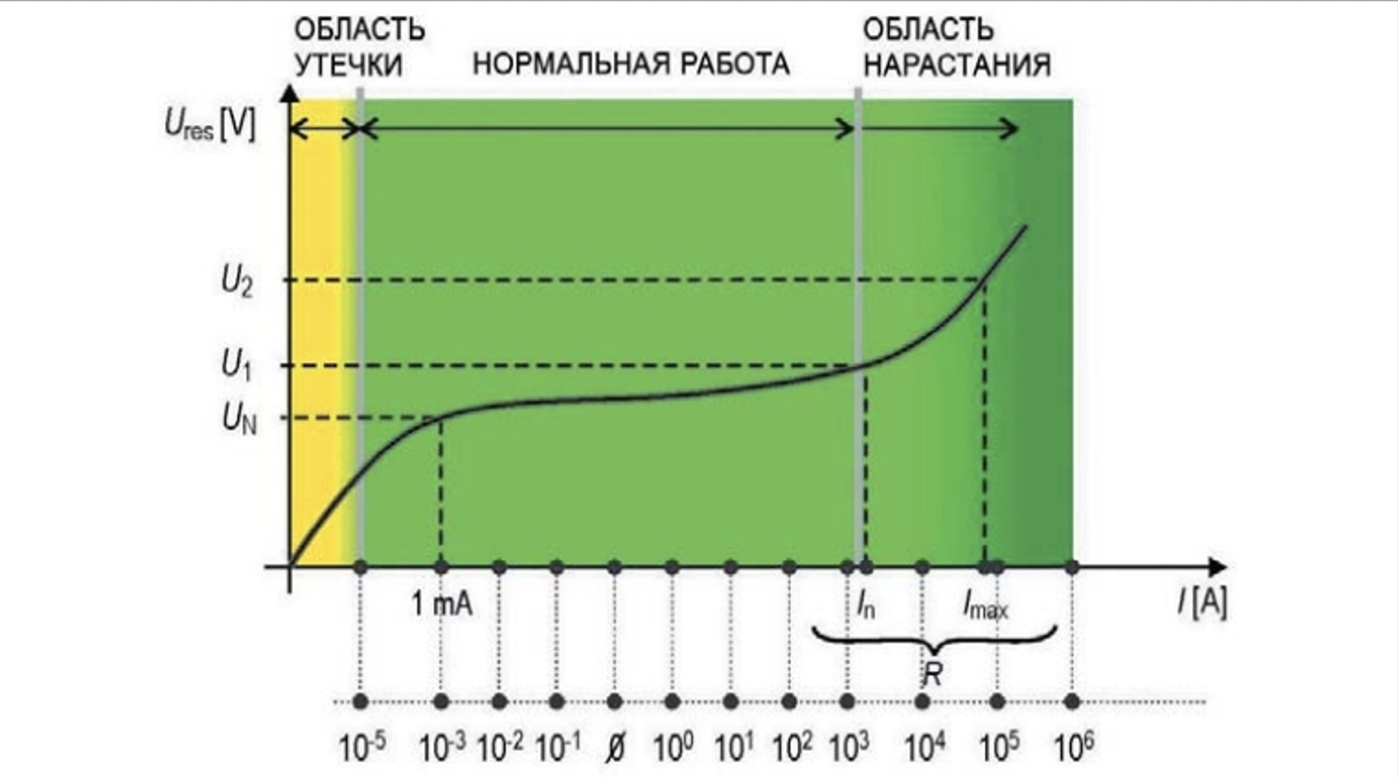
Fig. 2 Current-voltage characteristic of the varistor-based SDPs (limiting-type SDPs)
stabilizes and nearly does not change along with the current growth up to 1-10 kA. This is an operating section of the characteristic used to protect against surges. In case of a further current growth, the varistor overheats and the stabilization mode is disturbed.
In the production respect, this section provides all necessary information. Two SDP types, of switching and limiting type, provide the contents of any multi-page catalogue. All the remaining space is taken by technical specifics that have appeared in response to particular requirements of particular technical facilities and the need to consider their operating specifics in storm conditions. These requirements differ not only in details but also in principal process manifestations. Their objective consideration allows choosing the most suitable SDP type and defining its parameters which ensure a reliable protection against the surges, without any unjustified excessive features.
What does a modern equipment require from the SDP?
The most typical tasks, which can be solved by the SDPs in various technical facilities, are provided below. The device design becomes increasingly complicated along with the task, which is reflected in its cost and operating reliability in the electrical circuit of the protected facility.
1. The protected facility should remain intact.
Nothing else is needed. I could have given an example from my own practice by telling you how we protected the laboratory pulse diodes in the old times, since they were hard to obtain and very expensive. But I would rather talk about the trivial task to protect household appliances used in an individual house. During the lightning strike, the pulse interference in the 220 V mains can bring multiple electronic devices out of operation if nobody disconnects them from the mains. A short interruption in power supply does not entail any danger for the house, and a temporary pause in household appliance operation can be tolerated. Why do we need SDPs then? It is only sufficient that the SDP would prevent surge getting into electronic units. Fig. 3 shows a principal protection diagram.
At the input of the protected device, two pulse diodes connected back-to-back with a back voltage largely exceeding the rated voltage of the power electrical circuit are provided. One of the p-n junctions of these diodes is closed and does not pass the current along the bypassing circuit. Under the surge effect, the closed
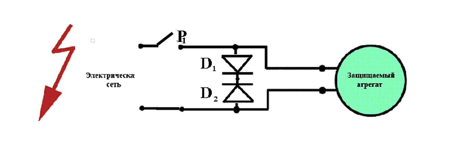
Электрическая сеть - Electrical mains
Защищаемый агрегат - Protected unit
Fig. 3 Elementary diagram for device protection from the damage due to a surge interference
junction is broken through and a bypassing circuit shorts out the input of the protected device thus excluding its damage. In this case, the diodes themselves can be permanently damaged. The short-circuit current that flows through them and that will be disconnected after the surge fade by a conventional upstream breaker P1. The power supply is interrupted and the normal operation of the protected equipment will be disrupted. This is not a good situation for anyone. The main goal will be achieved since the equipment will not be damaged.
2. The protected equipment should remain intact and operational.
The above-mentioned primitive device made of the diodes connected back-to-back is not suitable for this. The barrier is the short-circuit current that will flow through them after the breakthrough. A conventional breaker will interrupt the power supply and normal operation of the equipment will stop. It is time now to recall varistor-based. limiting-type SDPs. Upon the surge exposure, it does not reduce its input resistance to zero but merely limits the surge value. This is done very quickly, for several dozens of nanoseconds. The upstream breaker will not be able to trigger within this time. Almost this quick, the varistor will return to its initial non-conductive state. The electrical circuit will proceed with its operation.
Seems like we should not desire anything more. But this does not always happen like this. The lightning has found a weakness in a varistor. With its typical dimensions, the stabilizing action of the varistor is disrupted even with the current not exceeding 10 kA. Then, the voltage sharply increases (see Fig. 4) and can exceed the electrical strength of the protected equipment. Here, we have to be careful. The fraction of the current passing through the varistor should be estimated with high credibility. It should in no case exceed the values typical of the stabilization section of the current-voltage characteristic. An issue of current estimation for SDP is considered in more details below.
The lightning also uses internal infiltrators. In its struggle with the varistor-based SDPs, low voltage quality in 0.4 kV distribution grids helps it successfully. Due to phase imbalance, the phase voltage can be increased, e.g. to 270-300 V instead of allowable 230 V. In this case, the varistor current will exceed 1 mA. This can be for hours, which leads to heating a zinc oxide washer. Due to a low volume and plastic enclosure, the washer heat nearly does not drain and it eventually destroys mechanically. After that, nothing can limit surges. SDP becomes inoperable.
3. Varistor-based SDP should operate in low voltage quality grids.
The most feasible aspect is to improve the voltage quality. However, lightning protection specialists cannot do that. Only SDP improvement can help. Probably, it cannot be used in an electrical circuit permanently. We can use the example with an old woman as described above. Let her look at the clouds, and when she sees a storm, she can turn on the SDP. Unfortunately, this system has a low reliability, because the old woman's memory is poor. Automated equipment is more reliable. A practical option of the required device is shown in Fig. 4. An arrester, typically gas-filled , is connected in series with a varistor. By selecting the length of an insulation gap, the composition of the gas mix, and the pressure, we can provide the arrester breakthrough voltage slightly above the voltage of the electrical mains considering possible phase imbalance. Then, the varistor will be insulated from the increased voltage and cannot be overheated. The spark gap will be broken through only by the surge, will turn on the varistor and protect the equipment. After the surge fading, the varistor will interrupt the current and blow out the arrester. The circuitry will get back to its initial state. In this device, the varistor
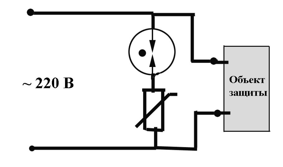
Объект защиты - Protected facility
220 В - 220 V
SDP scheme with a varistor connected through a gas-filled arrester
cannot be damaged due to overheating. It is simply not connected to the electrical circuit in a stationary mode. Naturally, the varistor and the arrester are located in a single enclosure that does not differ much from the enclosure of a conventional breaker and can be installed in the same mounting rack.
4. SDP should remain operating in case of maximum currents.
This task is typical for the most critical facilities where high reliability of operation of the electronic equipment in storm is required.
We should consider that the space in the mounting cabinet is limited. There is always some lack of space in the cabinet. Specialists try to locate all SDP elements in the enclosure that can be installed on a typical mounting rack. The working space in the SDP is thus dramatically limited. Both zinc oxide washer and glass enclosure of the arrester have limited dimensions. Both can be mechanically destroyed in case of high fraction of the lightning current flowing through the SDP. Operating experience and laboratory tests have shown that we can hardly count on the current flowing through the SDP and being much more than 10 kA in this case. Is it sufficient for the most applied problems related to critical facilities?
The situation is the most difficult when the lightning current goes to the ground along the minimum amount of conductors, usually two (a single-phase two-wire line). The Russian regulatory documents for lightning protection and the IEC 62305 standard set the estimated lightning current depending on the protection level. Even for the weakest levels III and IV, its magnitude is taken as 100 kA (50 kA per each wire). It is clear that SDPs with the allowable current equal to about 10 kA are not suitable in this case. It is also not suitable for a three-phase 4-wire circuit, where the lightning current 100 kA is divided in the wires by 25 kA. SDP manufacturers often do fakes by forcing the lightning current distribution in the way most suitable for them. The reader can read more about this technique in the above-mentioned section on the calculation of the current loading the SDP. Note that, in many situations, the varistor-based SDP cannot cope with the strong lightning. Allowable current flowing through it can be increased.
As noted, there are two weak elements. Both varistor and gas-filled arrester give in to great currents. Thus, both elements should be removed. The varistor was used to avoid short circuits. However, the problem will not be relevant any more, if we provide the SDP with an arc-suppression chamber.. They have been successfully used for a long time, e.g. in air high-voltage breakers. To cut off the electrical arc between the breaker terminals, a gas blast is provided. The gas flow extends and cools down the arc until its full suppression. Something of the kind can also be done in the SDP chamber. But this problem is challenging due to very small dimensions of the device. Each manufacturer can solve it in its own way. Fig. 5 shows cross-sections of the two chambers. One of them (chamber A) uses the RAC technology. According to the technology, the arc channel is divided into a series of spark gaps, and in each of them, an electrode sheath voltage drop occurs. When their total sum exceeds the operating voltage of the power circuit, the follow current blows out. Chamber B implements the RADAX Flow technology. It is made of a special gas-generating material. When it contacts a hot arc channel, it creates a gas flow. The arc extends along thin inner channels and therefore blows out in a relatively low rated voltage of the electrical mains. Typically, it happens very quickly, during the first half-period of the operating voltage. For a short blowout time with the short circuit current 50 kA, even a 20 A fuse has no time to blow out (it is intentionally included into the circuit for the tests performed for advertising purposes)!
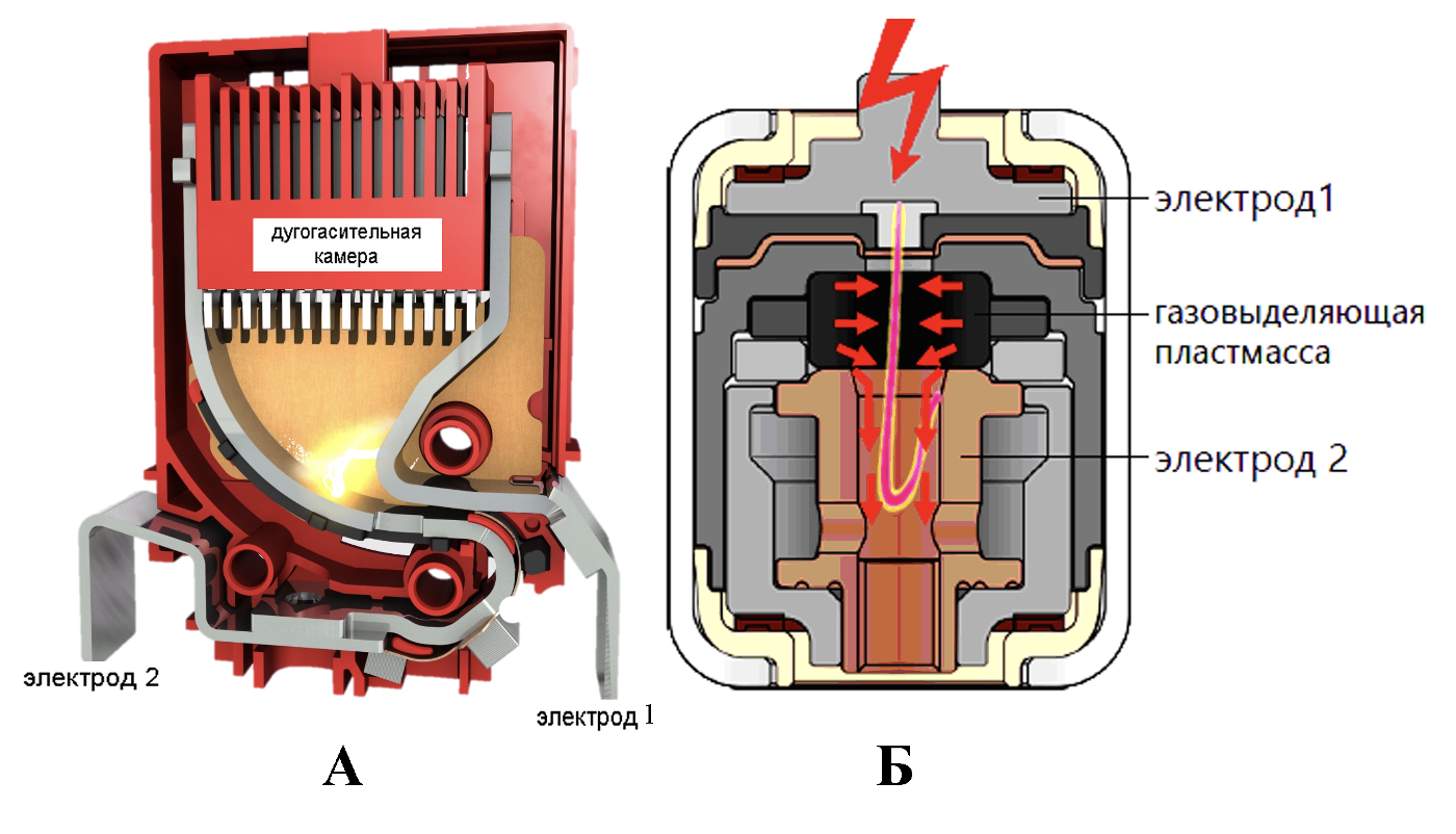
Электрод 1 - Electrode 1
Электрод 2 - Electrode 2
Дугогасительная камера - Arc-suppression chamber
Газовыделяющая пластмасса - Gas-emitting plastic
Fig. 5 Implementation example of arc-suppression SDP chambers
It is very technologically challenging to develop a good arc-suppression chamber. The chamber is always a trade secret. There is no point in comparing different solutions in this article. Note that today, the follow short-circuit current 50 kA can be successfully blown out by a mass-produced SDP, and thus we can refrain from using a varistor, at least in the maximum capacity devices.
If we refrain from the varistor, a gas-filled arrester is also of no interest. It cannot pass large pulse currents of the lightning. An air-gap arrester is much more reliable, as it can operate with a pulse current that is larger at the order of magnitude. The 100 kA current is not a limit for it. To reduce the pickup voltage for this arrester, a three-electrode system with a forced ignition is usually used.
Small air-gap spark arresters intended for large lightning currents have been successfully developed by a series of foreign companies. Their arc-suppression systems successfully deal with the short-circuit follow currents up to 50 kA.
5. The damaged arrester should not stop the protected equipment operation.
There is no reason to doubt in the proverb: “One leg of a mutton helps down another.” While air-gap spark arresters have expanded the operating range of the lightning current and successfully dealt with large follow short-circuit currents, they still do not ensure an absolute reliability. Any technical device can fail at any time. And not in all cases disconnection of the damaged electrical circuit may be entrusted to the electromechanical upstream breaker. The point is not only in its relatively slow action. When the breaker is triggered, it cuts off power supply of the protected equipment and stops its normal operation. This is often unacceptable. The solution is obvious: the SDP in the circuit must contain a power fuse (Fig. 6).
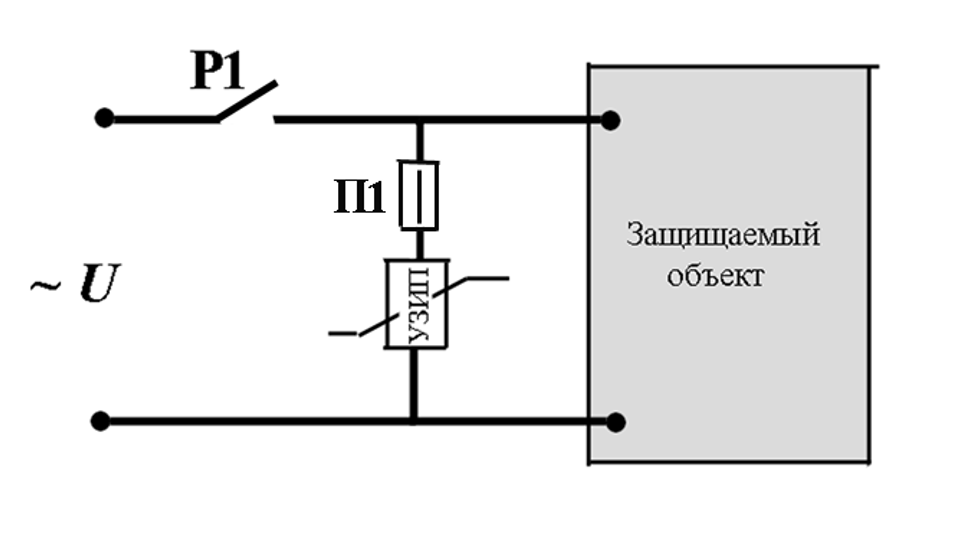
Защищаемый объект - Protected facility
УЗИП - SDP
Fig. 6 Switching-type SDP with a fuse
It is possible to choose the fuse that can pass the required pulse current of the lightning. Experimental data shown in Fig. 7 have been taken from [1] and allow estimating limit values for the lightning current 10/350 mcs, which cause combustion or even explosion of the fuse. There is a different issue. What will the fuse do upon the follow short-circuit current exposure? The lightning current in Russia is determined by the Prophet Elijah rather than people, and the short-circuit current is determined by the transformer that has been installed at the substation by the personnel. They can hardly align these currents.
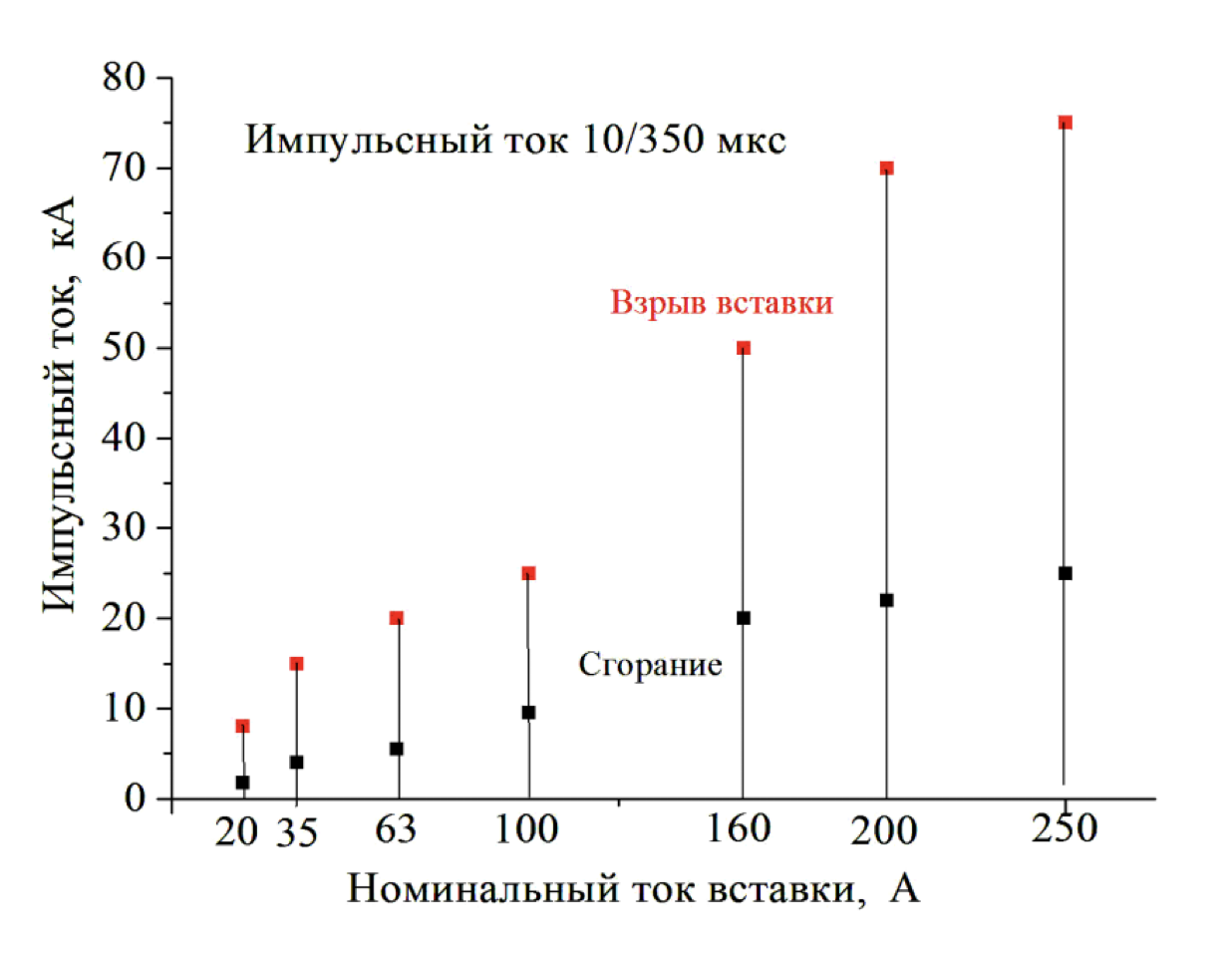
Импульсный ток, кА - Pulse current, kA
Импульсный ток 10/350 мкс - Pulse current 10/350 mcs
Взрыв вставки - Fuse explosion
Сгорание - Combustion
Номинальный ток вставки, А - Rated fuse current, A
Fig. 7 Pulse characteristics of the gG fuse for the current 10/350 mcs
If we choose a fuse with some reserve in terms of the pulse current, it may fail disconnecting the short-circuit current. The choice made by the short-circuit current may lead to false triggering of the fuse from the pulse lightning current, which would not be dangerous for the SDP. We have to choose the lesser of two evils.
The technical guidelines draw attention to the choice of the fuse in terms of lightning pulse current but they, for some reason, ignore its operational analysis in case of a break-up of the follow short-circuit current. This is extremely thoughtless. By reacting to the short-circuit current, the fuse must react to it before the upstream breaker. Otherwise, the power supply to the protected device will be disconnected instead of disconnecting the damaged SDP. This operation in this section is considered to be completely unacceptable.
Any fuse blows out with the delay in time required for its heating up. This time is reduced along with the increase in the current flowing through the fuse. The reduction rate is determined by the current-voltage characteristics. It is shown in Fig. 8 as an example for gG multi-purpose fuses. The upper horizontal row in the curves provides rated fuse currents. To react before the upstream breaker,
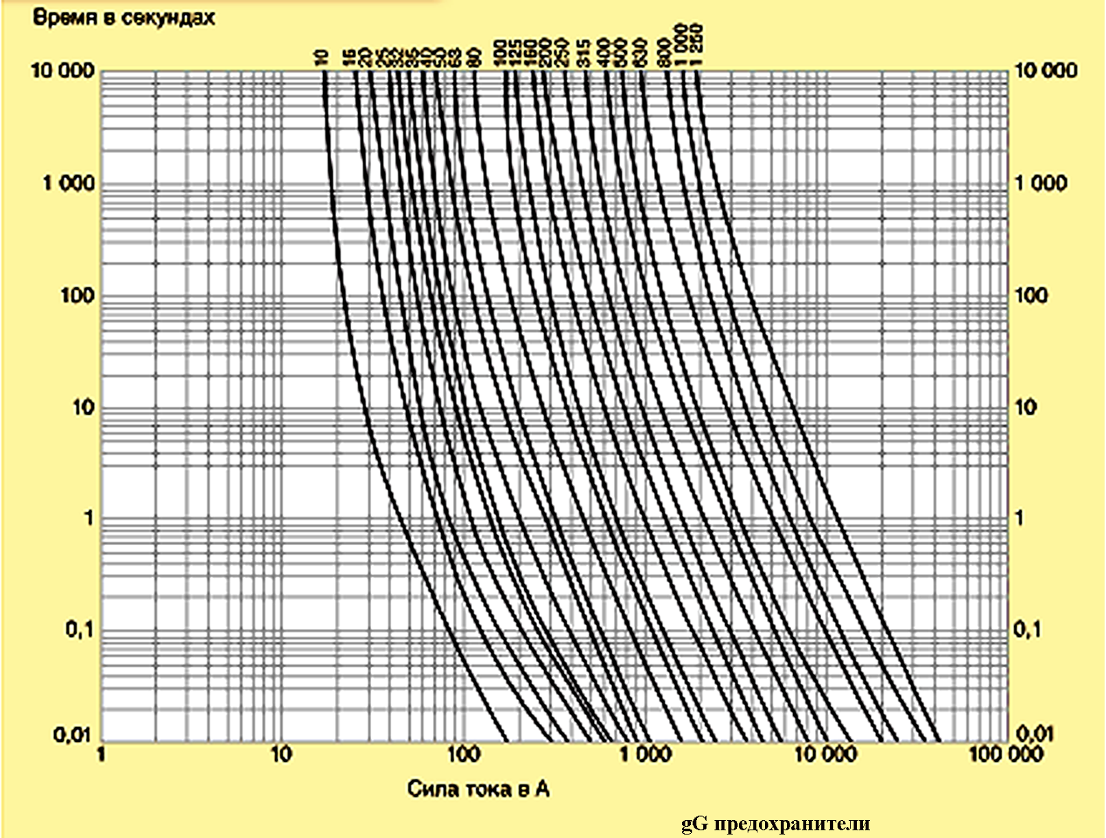
Время в секундах - Time (sec)
Сила тока в А - Current, A
gG предохранители - gG fuses
Fig. 8 Current-time characteristics of conventional gG fuses
the fuse should blow out within at least 0.01 sec. The current required for this can be easily found in the curves shown in Fig. 8. Thus, for the 100 A fuse, the short-circuit current should be somewhat above 2,000 A, and for the 315 A fuse, it should be 10,000 A. It can be unavailable due to low power of the feeding transformer. The fuse will not have enough time to react. It will be left behind by the upstream breaker, and the power supply of the protected facility will be interrupted. Since this is unacceptable in the considered problem, we have to voluntarily choose a fuse with a lower rated current. Because of this, the protecting device will not provide a 100% reliability. With sufficiently large but completely safe for SDPs lightning currents, it will be mistakenly cut off by the blown-out fuse and leave the equipment without protection.
As you can see, there is no perfect solution.
6. SDP should protect the equipment with a low electrical strength
No particular problems are envisaged if the lightning current fraction in the electrical circuit is low just as the follow current. Then we can use a gas-filled arrester with a varistor or an arrester based on pulse semiconductor diodes (TVS diode, suppressor, semiconductor voltage limiter — these are the names used in the reference sources). As noted, diodes use avalanche breakdown of the p-n junction that quickly restores its properties after the high voltage release. Bi- and unidirectional diodes are distinguished (Fig. 9). The latter can work with a single-polarity voltage.
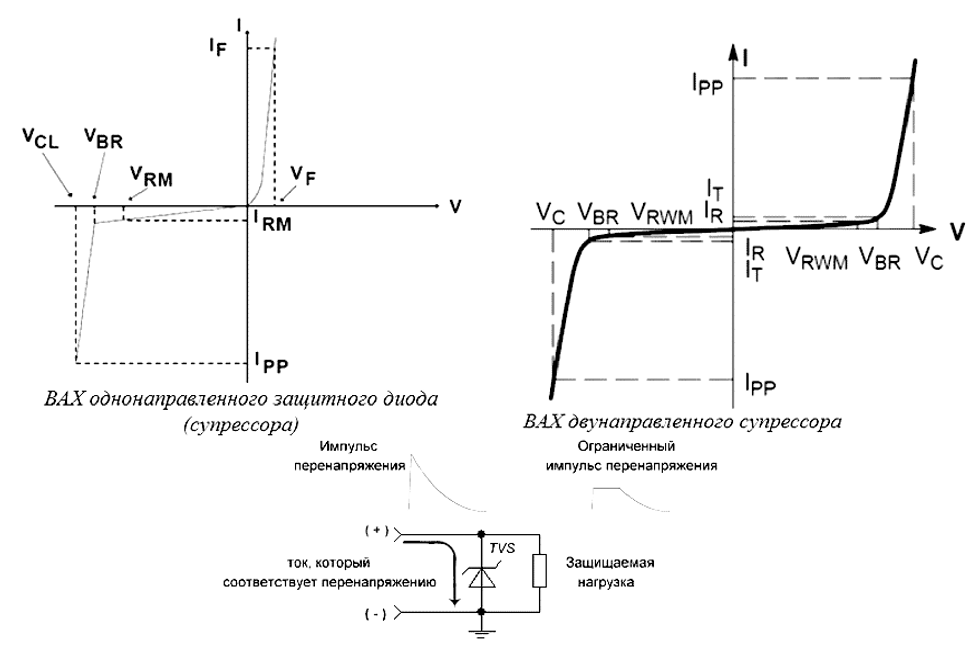
ВАХ однонаправленного защитного диода (супрессора) - Current-voltage characteristics of a unidirectional protective diode (suppressor)
ВАХ двунаправленного супрессора - Current-voltage characteristics of bidirectional suppressor
Импульс перенапряжения - Surge pulse
Ограниченный импульс перенапряжения - Limited surge
Защищаемая нагрузка - Protected load
Ток, который соответствует перенапряжению - Current corresponding to the surge
Fig. 9 Current-voltage characteristics of the protective semiconductor diode
Due to a low triggering time (fractions of a nanosecond), the diode limiters are primarily used in high-frequency circuits and to protect microcircuitry. This is also promoted by their low capacity (up to fractions of a picofarad in case of low passing current) and small dimensions. The range of modern diode limiters is very broad as well as a range of electrical parameters. In terms of operating voltage, they cover the range of several units to hundreds volts. The range of currents, which are passed by the diodes in the breakthrough mode, is also broad (up to several hundreds of amperes). Though, the increase in the discharge capacity inevitably leads to the increase in the parasitic capacity of the p-n junction, which limits the application of the device in high-frequency circuits.
The situation becomes different when the electronic unit is installed in a powered electrical mains, and its own electrical strength is significantly lower than that of the rest of electrical equipment; e.g. it does not exceed 1.5 kV, while the electrical circuit can withstand 4 kV. It is clear that we cannot avoid Class I SDP here, with the interference limited at 4 kV. Further, we will have to reduce it to at least 1.5 kV, which is typical of the Class III SDP. Even until recently, the problem was solved straight away. After air-gap spark arrester-based Class I SDP with an efficient arc-suppression chamber, a varistor-based Class II SDP was installed, after which, if necessary, a varistor- or pulse diode-based Class III SDP was also installed. In such a staged system, the first SDP absorbed a major fraction of energy delivered by the lightning current. The other two nearly did not dissipate energy and adjusted the interference voltage to the safe level.
The principal diagram of a serial SDP connection is shown in Fig. 10.
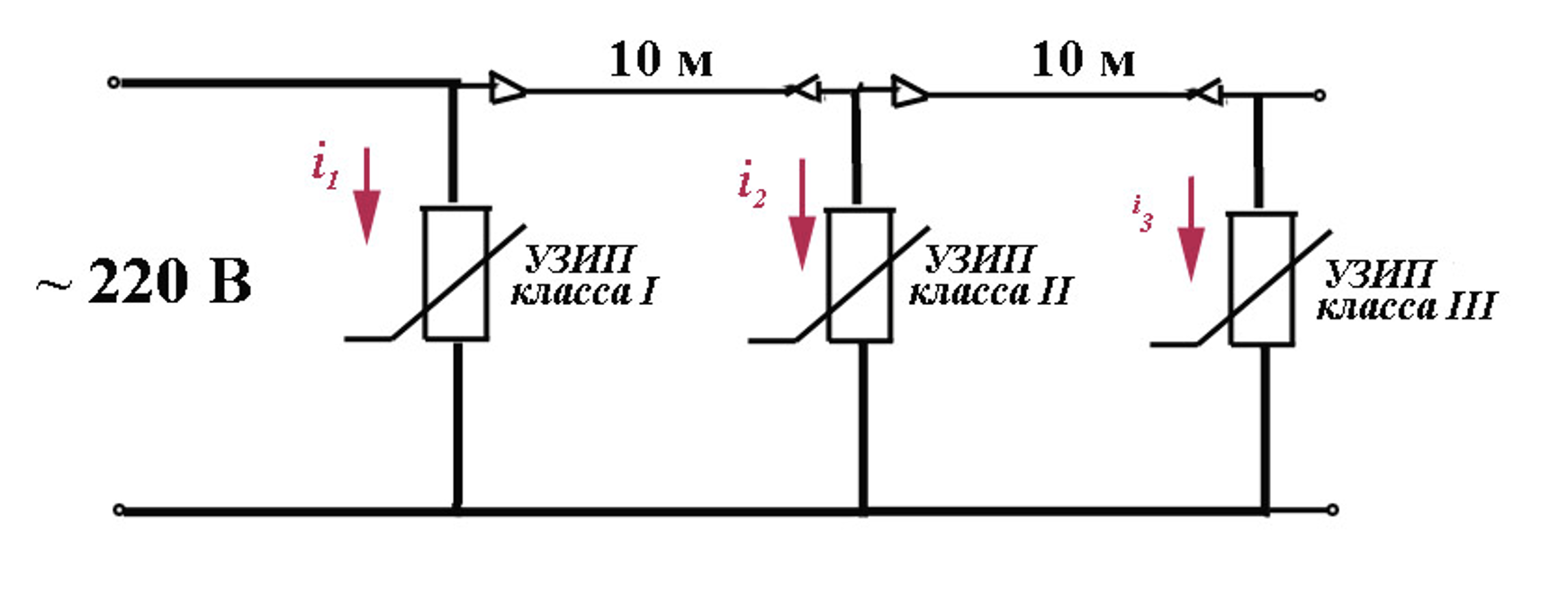
Fig. 10 Protection using serial SDP connection
I have to remind once again about the lack of space in mounting cabinets. Here, we should install three instruments instead of one but also about 10-meter cable sections or concentrated coils with a similar inductance. They are required to provide a selective operation of SDPs that should be turned on strictly one after another for Classes I to III. This is an obviously unattractive idea.
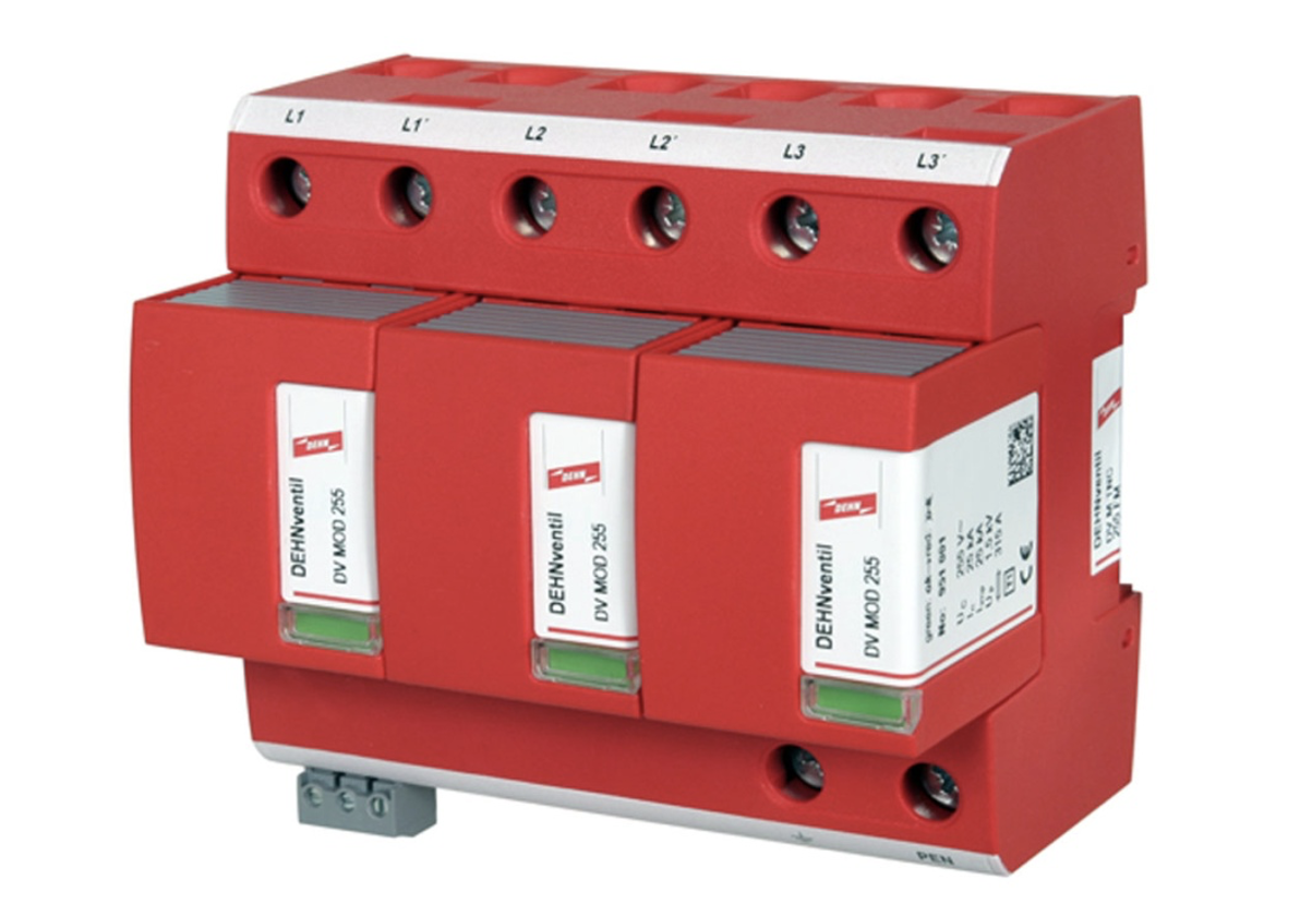
Fig. 11 Class I + III SDP
An SDP developed using a modern technology is shown in Fig. 11. The class of this instrument should be designated as I + III. This is based on the following parameters:
- pulse current 10/350 mcs: 25 kA per phase;
- rated discharge current 8/20 mcs: 25 kA per phase;
- arc suppression of the follow current: up to 50 kA;
- protection voltage level: less than 1.5 kV.
The arc-suppression chamber of the SDP has been created according to the above-mentioned technology RADAX Flow. Saving in the mounting space and significant increase in the operational reliability are clear.
Saving in the operating space in the mounting cabinet determines the design of the major part of modern SDPs. One enclosure combines not only a controlled arrester and an arc-suppression chamber. Often, it also houses a fuse having optimum parameters. All of these naturally increase the instrument's value. Therefore, it is important to properly determine your own needs and avoid excessive spends. The protection scope is likely to be defined by the customer. He or she knows the technology that should be implemented by the protected equipment. This helps solving the problem of choosing the SDP type, but not evaluating its parameters, primarily in terms of the maximum allowable lightning current. We cannot avoid calculations in this case. The method for pulse currents was developed as early as in the beginning of the previous century and does not pose any problem for the modern computing equipment. However, this issue deserves more attention, because, in official sources, recommendations have appeared for the a priori estimation of the fraction of the lightning current, which are thought to be not demanding calculations. Usually, the electrical engineering theory is completely ignored there, although it is well developed and proven by practice.
Related Articles:
 Lightning Protection of Large Territories: Parks, Grounds, Plant Territories. Page 1
 Lightning Protection of Large Territories: Parks, Grounds, Plant Territories. Page 2
 Lightning Protection of Large Territories: Parks, Grounds, Plant Territories. Page 3