Construction facilities are grounded to meet the requirements of electrical safety, fire safety and functional requirements for the electrical [4]. [5] and lightning protection systems [1]. Ground electrode systems are used to address a number of important tasks:
- ensuring the correct operation of the electrical system;
- compliance with the requirements for electrical safety (to ensure the proper functioning of devices for protection against electric shock);
- effective equipotential bonding of the facility system and the drainage of surges that occur, for example, as a result of atmospheric discharges;
- drainage of short-circuit and leak currents to the soil;
- safe dissipation of lightning current drained from the lightning
- protection system (LPS) in the soil.
Design principles of lightning protection ground electrode system are set forth in PN-EN 62305-3: 2011 [1] standard. This document defines two types of ground electrode systems (Fig. 1):
- type A circuit made up of a system of horizontal and vertical ground electrodes mounted outside the construction facility;
- type B circuit as a closed, meshed or foundation loop.
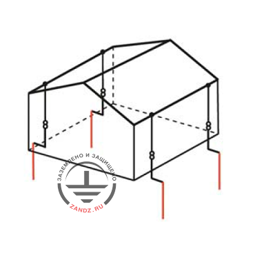
Type A ground electrode system
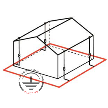
Type B ground electrode system
Fig. 1. Ground electrode system types as defined by PN-EN 62305-3
The resistance of ground electrode system is the criterion of grounding system efficiency. In general, unless special requirements for construction facilities exist it is recommended that this parameter would not exceed 10 ohms. To meet the requirements of modern lightning protection standards is sufficient to determine the minimum length of ground electrode system l1 as shown in Fig. 2; a value of 10 ohms discussed above is deemed a general recommendation.
Fig. 2 means that the minimum value l1 depends on the specific resistivity of the soil ρ, as well as on the level of lightning protection system (LPS). However, length l1 may be omitted as a criterion if the active grounding resistance is less than 10 ohms.
To ensure electrical safety at special facilities such as transformer substations a smaller value of resistance may be required. For example, PN-HD 60364 series of standards for low-voltage electrical systems recommends that the active resistance of grounding conductive parts at a transformer station should be less than 1 ohm [4].
Considering only the grounding length criterion according to charts shown in Fig. 2, the minimum length of each type A ground electrode system from the base of down conductor should be equal to:
- l1 for horizontal ground electrodes,
- 0,5 l1 for vertical or sloping ground electrodes.
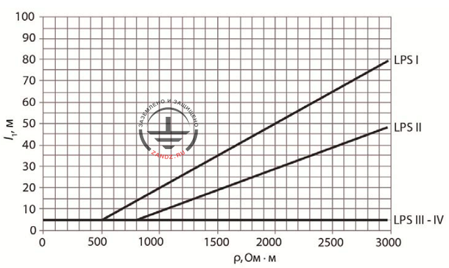
Fig. 2. The minimum length l1 of each ground electrode system according to LPS level
When using composite ground electrodes (horizontal and vertical ones) it is necessary to take into account their total length. The total number of ground electrode system shall be at least two.
In type B circuits, the ground electrode system criterion is the average radius re of a segment covered by the ground loops or foundation ground electrode system. This rate should not be less than the required minimum length of the ground electrode system: re ≥ l1.
If this condition is not met (i.e. re)
lr = l1 - re for additional horizontal ground elecrodes or
lr = (L1 - re) / 2 for additional vertical ground electrodes.
Additional ground electrodes should be placed in the places of LPS down conductor connection, and if possible at equal distances along the type B ground electrode system loop.
In practice, the expansion of grounding system with optional horizontal and vertical ground electrodes is rather frequently used to achieve small active grounding resistance required by the design documentation. Another commonly used method to reduce the grounding resistance is driving deep vertical electrodes into the soil.
Related Articles:
