The ubiquity of foundation ground electrode systems in Poland is the result of requirements enforced by the Decree of the Minister of Infrastructure dated 12 April 2002. [2] On the technical conditions for buildings and their location. According to §184, paragraph 1 [2] "Metal structures of buildings, foundation reinforcement bars, as well as other metallic elements of non-reinforced foundations that represent an artificial foundation grounding should be used as a ground electrode system".
Other regulatory documents relating to both electrical and lightning protection systems also recommend using foundation ground electrode systems. The main reasons that experts prefer such electrode systems is that they are inexpensive and easy to implement, foundations have a good contact with the soil, the active resistance of foundation (i.e. the dependence of foundation resistivity from the changes in temperature and humidity is negligible), and its surface is fully utilized to dissipate ground currents.
Considering that the foundation ground electrode system consists of steel components cast into the concrete, it is necessary to pay special attention to the quality of metal elements connection in order to ensure the continuity of current flow. In the practice of construction works, the rebars of reinforced concrete structures are most often connected together with binding wires. 5).
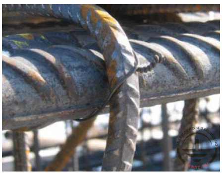
Fig. 5. Connecting rebars using binding wire (courtesy of RST sp.j.)
In this regard, if the foundation needs to be effectively used as a natural ground electrode system, the rebar connections should have a low resistance. To ensure the certain electrical connections of rebars, it is recommended to additionally embed a wire mesh made of metal rods or tapes in the foundation (Fig. 6) and connected the to rebar steel with bolted clamps. Welded joints are even stronger.
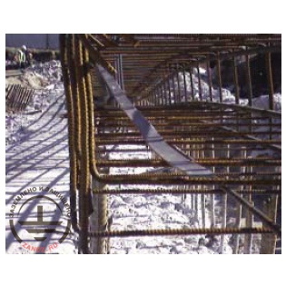
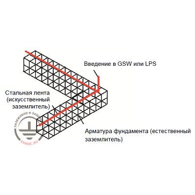
Fig. 6. The recommended implementation of a foundation ground electrode system using steel tape (courtesy of RST sp.j.)
All works related to the additional connection of rebars must be agreed with the designer of the foundation to ensure that the strength of the foundation meets the design requirements.
A significant advantage of the foundation ground electrode systems is active grounding resistance that remains stable over time. This topic has been well described by the example of construction projects in progress [6]. The stability of active resistance of the foundation ground electrode system is affected by the fact that foundations are usually surrounded by the soil with a lower resistivity than the surface layers; the resistivity of deeper layers of the soil is less dependent on the time of year and the weather. The foundation ground electrode system in buildings with several underground levels is located below the lowest floor, so the changes of soil temperature and humidity at these depths throughout the year are so insignificant that they can be neglected.
Connecting foundation ground electrode systems with additional electrodes
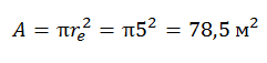
Using the foundation as the only element of ground electrode system has certain limitations related to its size or the resulting active ground resistance. Thus, in case if the facility that requires lightning protection is installed on a foundation with a small surface area, such as tower antennas, single-family homes or small technical facilities, it may happen that the criterion of the minimum dimensions of the foundation is not met. This means that the average radius of equidimensional surface RE of a territory covered by the foundation ground electrode system cannot meet the requirements of
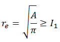
PN-EN 62035-3 lightning protection standard. For level III and IV lightning protection systems typical for such facilities, the required minimum length of ground electrode system is l1 5 m (Fig. 2), which corresponds to the surface
Small foundation ground electrode systems
In addition, in special facilities, such as a free-standing switchgear or kiosk package transformer substation, foundation ground electrode systems may prove an insufficient solution to provide the desired small active grounding resistance due to the small size of the foundation.
Moreover, connecting all supported devices to the facility with a foundation ground electrode system may either significantly complicate the measurement of ground resistance or it will have to be done manually as a result of operational complications. In practice, this problem is related to the lack of appropriate instrumentation connections, as well as inability to disconnect the serviced devices from the ground electrode system at the time of grounding resistance measurement.
The above problems related to the foundation ground electrode system can be successfully solved by applying additional artificial ground electrodes, which help satisfy the condition re ≥ l1 or achieve the appropriate active grounding resistance. An example of such solution for the foundation ground electrode system of a small external transformer station is shown in Fig. 7. Adding one or more auxiliary ground electrode systems with respective test terminals the way it is shown on the figure facilitates carrying out periodic measurements of foundation grounding active resistance.
Read previous
"Requirements to the grounding elements"
Related Articles:
