From the series of articles "Grounding resistance calculation is almost easy".
The best thing here is to consider specific examples, starting with the simplest one.
Horizontal ground bus in the ground at depth h
Example 1. In the figure, a horizontal bus of length l in the ground at a depth of h. In the upper half of the figure is its mirror image. As recommended above, we will solve the problem for a current I=1 A. Then the linear leakage current density is equal to
J = 1/l
Not only the radius of the bus, but also its laying depth in the ground h << l. So, combining zero point of the coordinate axis with the tip of the bus in the ground, to calculate the components of the potential, you can use the simplified formula (7). For the potential component of the current of the bus itself, given that r=r0, and J=1/l, we obtain

(9)
and for the component from the mirror reflection taking into account r=2h

(10)
The full potential is equal to the sum of its components

(11)

(12)
Example 2. In the figure, a lightning conductor ground electrode recommended for use without restrictions by the Lightning Protection Instruction RD 34.21.122-87. Unfortunately, its grounding resistance is not indicated in the text of the standard. Let’s eliminate this misunderstanding. In the upper part of the figure there is a plane reflection of the electrodes in a flat boundary, with all dimensions and direction of the leakage current that flows into the ground from the grounding electrodes, remaining unchanged.
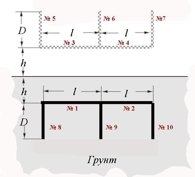
Grounding switch from RD 34.21.122-87
Грунт - Soil
For convenience, they are all numbered. Reference point for calculating the potential is selected on the side surface in the middle of electrode No. 1. I remind you that the coordinates of the electrodes with current and the coordinate of the calculated point that are entered into formula (6) to determine the components of the potential can be set relative to an arbitrary axis, for convenience it is desirable to be parallel to the conductor with current. Therefore, to calculate the potential components from horizontal buses No. 1 - No. 4, the coordinate axis was drawn from the beginning of segment No. 1 and went along it in the direction of segment No. 2, and for the remaining electrodes (vertical), the axis proceeded from the upper end of segment No. 5 and went vertically down .. It was assumed that all electrodes have the same radius r0 .. The values of the parameters that were introduced into formula (6) for calculating the potential components of the current of each electrode are presented in the table for the convenience of calculation monitoring. In the same column, the calculated values of the logarithm included in formula (6) are given for the potential components from each of the grounding electrodes. The calculations are made on a conventional scientific calculator for the dimensions of the ground electrode that corresponds to Instruction RD 34.21.122-87: l=5 m, D=3 m, h=1 m, r0=0.01 m.
Table for control of calculated data
|
Electrode number |
X1 |
X2 |
X0 |
r |
The value of the logarithm in the formula (6) |
|
1 |
0 |
l/2 |
l/4 |
r0 |
11,04 |
|
2 |
l/2 |
l |
l/4 |
r0 |
1,098 |
|
3 |
0 |
l/2 |
l/4 |
2h |
1,18 |
|
4 |
l/2 |
l |
l/4 |
2h |
0.796 |
|
5 |
0 |
D |
D+2h |
l/4 |
0.845 |
|
6 |
0 |
D |
D+2h |
l/4 |
0,845 |
|
7 |
0 |
D |
D+2h |
3l/4 |
0,589 |
|
8 |
0 |
D |
0 |
l/4 |
1,61 |
|
9 |
0 |
D |
0 |
l/4 |
1,61 |
|
10 |
0 |
D |
0 |
3l/4 |
0,73 |
Total: Log = 20.343
In order to obtain the final value of the potential, according to (6), one must also perform elementary arithmetic operations with the total value of Log

When calculating single current for the considered ground electrode, the average linear density of the leakage current from the electrodes is equal to

that for given sizes of electrodes gives J = 1/19, and
U= 20,343/19/12,56×ρ ≈ 0,085ρ.
When calculating single current, found value is numerically equal to the ground resistance. So,
Rg≈ 0,085ρ
It has to be noted that the discrepancy with a more accurate calculation, taking into account the change in the linear density of leakage currents in grounding electrodes, is within 6%. Accuracy is sufficient for designing. As it was promised, the utilization factors for the calculation were not required.
Where do they come from? The main source is calculations similar to those just performed, moreover, they must be performed for each electrode system and for each set of geometric dimensions. It is impossible to understand why the utilization coefficients are needed if, for their determination, it is necessary to find the true values of grounding resistances first? Well, if you collect a kind of data base, it is better be for the ground resistances, but not for the utilization factors. They are simply useless.
I apologize to the readers, but I will always talk about computers. They changed the whole way of our production life, making available what we did not dare to write about, even in science fiction novels. A modern designer cannot work without computer calculations. This is a fact and, based on it, you can probably find two weeks of time to learn the basics of programming. Age is no disqualification. I started learning at 50, and my teacher was 23. I have no doubt that on this website you will find support in your decision to improve. As for the calculations of grounding resistance, we can hope that in the near future an approachable program for approximate calculations will be downloaded on this website, the algorithm of which is presented in detail in this article.
E.M. Bazelian, Doctor of Technical Sciences, Professor
G.M. Krzhizhanovskii’s Energy Institute, Moscow
Related Articles:
 5. Boundary between soil and air