E.M. Bazelyan, Dr. Sc. (Eng.), Professor;
Krzhizhanovsky Energy Institute, Moscow;
renowned Russian Expert in Grounding and Lightning Protection
Grounding Pulse Resistance This is probably the most known parameter and is probably the most useless one. This is what the ratio of the largest voltage at the grounding arrangement and the current amplitude flowing through it is called. This is a relative notion because current and voltage maximums do not coincide in time. The pulse resistance ambiguously characterizes the grounding arrangement: its value is strongly dependent on time parameters of the current pulse. It is hard to find an estimate parameter that could have been determined using the pulse resistance. For this, you need to know current grounding resistance that is determined by ratio of grounding voltage at the grounding electrode and the current at the same fixed time. In terms of physics, the parameter is an input impedance of the grounding arrangement.
To understand the behaviour specific of grounding electrodes upon pulse current spreading, Fig. 6 shows time dynamics of the input impedance for horizontal buses having the radius of 10 mm and the length of 100 and 200 m. Their stationary grounding resistances differ by almost 2 times, 2.2 and 1.2 Ohm in a soil with the resistivity 100 Ohm m (installation depth 0.5 m). The calculation is made for pulse current with the exponential wavefront of about 3 mcs, which is a rather typical pulse form for the first lightning component. We can make sure that, within first 10 mcs, the current input impedance of the bus does not almost depend on its length and almost have equal values. They exceed stationary grounding resistances by many times. The obtained result can be easily explained. Within this time, the lightning current has not yet penetrated the entire length of the horizontal buses under consideration. It simply "does not know" what the actual length is.
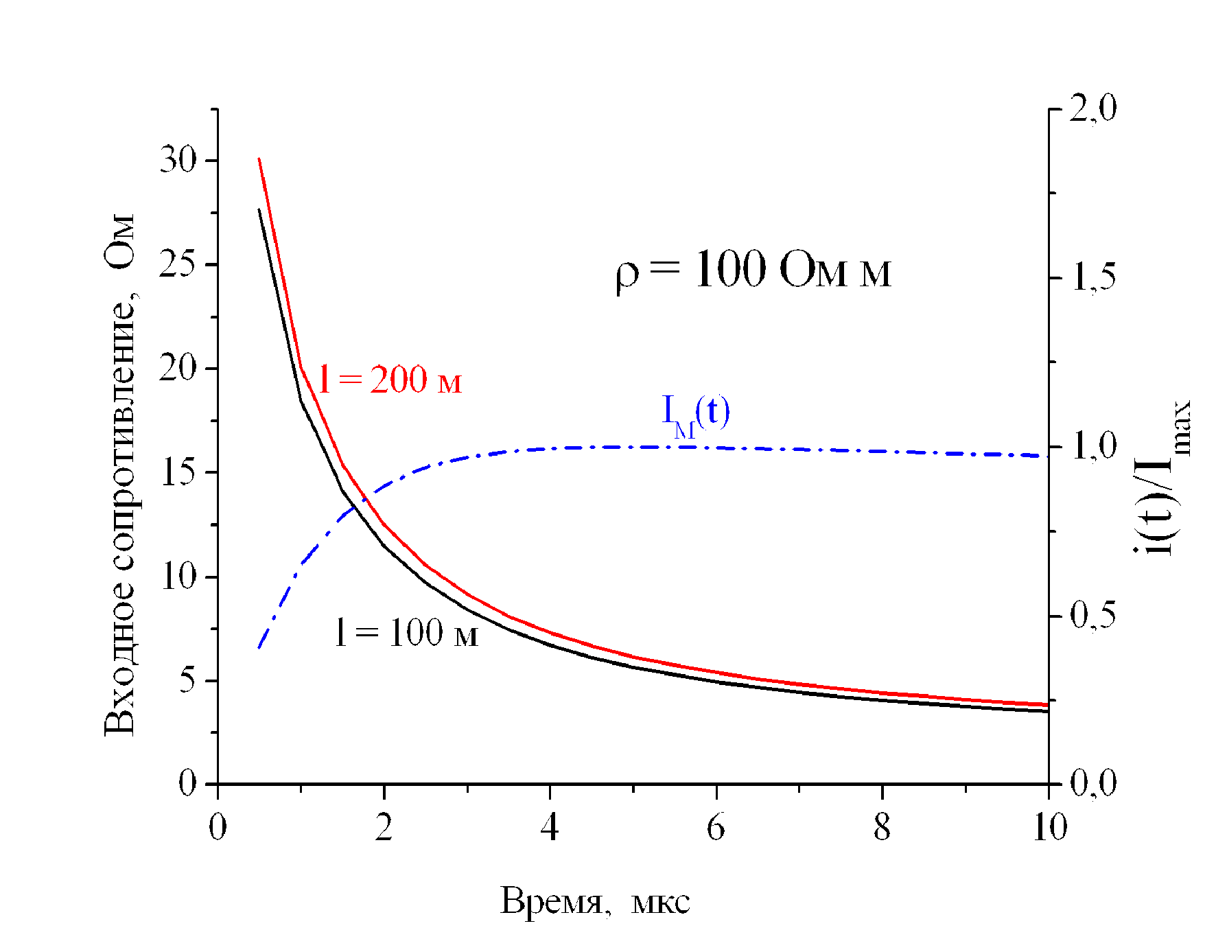
Fig. 6
Change dynamics of the input impedance of horizontal buses
Входное сопротивление, Ом - Input impedance, Ohm
Ом м - Ohm m
100 м - 100 m
Время, мкс - Time, mc
We can easily imagine the errors when calculating overvoltage, step voltage, or touch voltage when it is made using stationary grounding resistances without considering pulse characteristics. A clearly unsuccessful attempt to improve the grounding arrangement operation in the pulse mode due to increased grounding bus lenth is also annoying. The resistance time change dynamics should be known, and you have to know how to measure it in the current spreading with the time parameters that will actually load the grounding arrangement.
Problem of Measuring Grounding Resistance in a Pulse Mode
It is much easier to say than to do something. This is applicable to pulse characteristics of grounding devices to the fullest extent. Even in a concentrated scheme located on a mounting table or in a laboratory, we can find many error sources during pulse measurements. Thus, what can we say about a grounding device having an area of several thousand square meters!
This section describes measurements of the grounding resistance upon the lightning current flowing because they are the most significant problem. We have to start with the fact that the lightning is a peculiar current source. It has no return line. By flowing along the plasma channel into the lightning arrester and then to grounding electrodes, the lightning current goes to "infinity" by flowing across the volume of the Earth having the radius of 6,400 km. In any measurements, we have to simulate the lightning current with a pulse generator that has a return line. The magnetic field of this line will distort the pulse current distribution
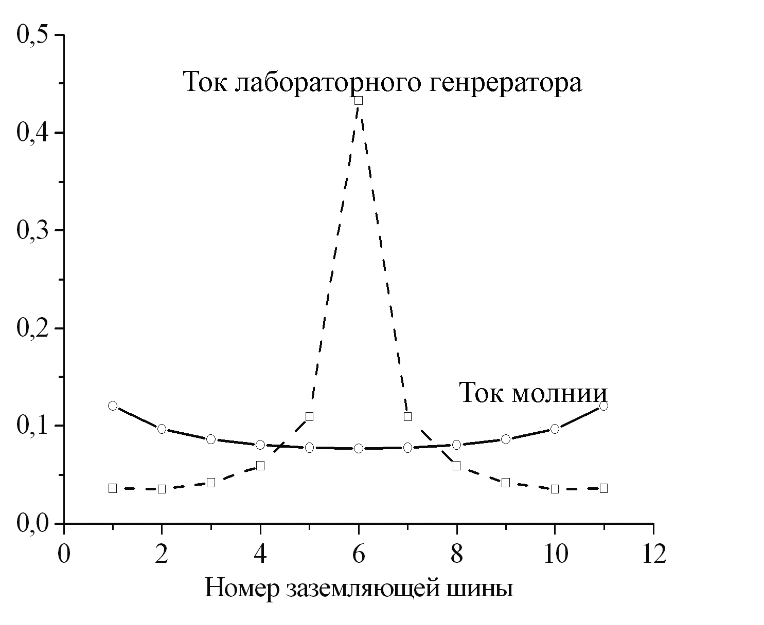
Fig. 7
Current distribution along the system of 11 parallel grounding buses of 200 m, radius of 1 cm installed with the step of 10 m.
Ток лабораторного генератора - Laboratory generator current
Ток молнии - Lightning current
Номер заземляющей шин - Grounding bus number
among grounding electrodes due to the magnetic induction electromotive force. Such re-distribution will change the measurement results. We are talking about errors of at least an order of several dozens per cent. An example of such distortions is shown in Fig. 7. Based on computer calculations, the current distribution in a system of similar parallel horizontal buses installed with the step of 10 m is plotted. You can see that, in the absence of a return line (lightning strike), the pulse current distributes among the buses in a nearly uniform way. It rapidly changes when the return line (laboratory measurements) is located over the central bus at the height of 1 m. Now, in the nearest central grounding bus, almost 45% of the total current is concentrated, and as long as the distance from the return line increases, the current decreae by more than an order of magnitude. Thus, the essential parameters such as grounding resistance, potential distribution across the grounding arrangement area and voltage between any underground utilities should change.
In practice, the effect of the return line can hardly be eliminated by increasing its height. Therefore, to decrease the current increase factor in the bus under the return line to at least 1.5, it should be installed higher by at least 20 m. This can hardly be made in real-life field conditions.
Evidently, the measurement error increases along with its length due to the effect of the return line. However, its harmful effects are not limited thereby. The inductivity of the return line changes time characteristics of the pulse source that simulates the lightning current, and the current amplitude also depends on it in full. An attempt to reduce the return line's length and also make away with the grounding electrode for an auxiliary current electrode has resulted in the development of a scheme shown in Fig. 8.
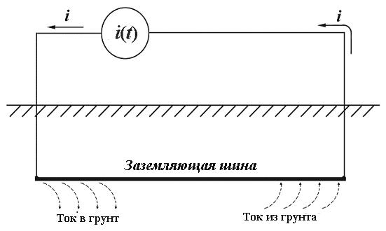
Fig. 8
Layout diagram of the measurement of the grounding pulse resistance without using the auxiliary current electrode
Заземляющая шина - Grounding bus
Ток в грунт - Current to the ground
Ток из грунта - Current from the ground
This idea seems to be very tempting. The ends of the laboratory source of the pulse current are connected to the most remote locations of the grounding arrangement. The current flows into the ground from one end and returns back to the source from another end. For some time, the current has not yet had enough time to penetrate the grounding bus for a full length and there is no its direct supply along metal. And one would think that this time can be used to measure the input impedance.
Related Articles:
 Lightning Protection of Large Territories: Parks, Grounds, Plant Territories. Page 1
 Lightning Protection of Large Territories: Parks, Grounds, Plant Territories. Page 2
 Lightning Protection of Large Territories: Parks, Grounds, Plant Territories. Page 3

