

Сектор энергетики содержит наиболее значимые объекты с точки зрения молниезащиты, в их числе: подстанции, электростанции и высоковольтные линии электропередач. Важна правильная организация молниезащиты не только на одном конкретном объекте, но и на всех объектах отрасли сразу, из-за того, что удар молнии способен привести, если не к катастрофе, то к значительным технологическим и коммунальным последствиям городского, областного или даже регионального масштаба. Возникают перерывы электроснабжения до обнаружения и устранения аварии, которые длятся, в зависимости от тяжести повреждений, от нескольких минут до нескольких дней. Разумеется, на всех этих объектах принято множество мероприятий и технических средств, которые не допускают удара молнии в критически важное оборудование, а также минимизируют последствия воздействия атмосферных разрядов.
К мероприятиям молниезащиты относятся:
- Молниезащита с помощью стержневых и тросовых молниеприемников, которые принимают на себя удар молнии вместо объекта. Также допускается применение кровли в качестве молниеприемника и сетки, если удар молнии непосредственно в объект не приведет к каким-либо значимым последствиям
- Правильное расположение молниеприемников и токоотводов, которое обеспечивает контролируемый отвод тока молнии в заземляющее устройство. В результате такой меры ток молнии в процессе растекания по объекту не сможет создать значительные электромагнитные поля и перенапряжения опасные для электрических и электронных устройств при наведении на питающие их кабели и вторичные цепи.
- Корректно спроектированное и надежно смонтированное заземляющее устройство - без него все остальные меры будут неэффективными. Необходима правильная конструкция заземлителя для того, чтобы ток молнии растекался в земле в достаточной степени, что должно привести к снижению величины перенапряжений, исключению поверхностных разрядов и искрений. Для правильной работы заземляющее устройство должно обладать определенным сопротивлением заземления, которое на подстанциях составляет не более 0,5 Ом.
К техническим средствам относятся:
- Ограничители перенапряжений, такие как разрядники и устройства защиты от импульсных перенапряжений (УЗИП). В высоковольтных сетях применяются разрядники и ОПН, а в низковольтных УЗИП.
- Автоматика восстановления питания после удара тока молнии, если удар не привел к необратимым повреждениям и нормальная эксплуатация может быть продолжена. Таким средством является автоматическое повторное включение (АПВ) на линии.
Подстанциям и высоковольтным линиям электропередачи уделено серьезное внимание в нормативных документах, среди них:
- Правила устройства электроустановок (ПУЭ).
- СТО 56947007-29.130.15.114-2012 “Руководящие указания по проектированию заземляющих устройств подстанций напряжением 6-750 кВ”.
- РД 153-34.3-35.125-99 “Руководство по защите электрических сетей 6 -1150 кВ от грозовых и внутренних перенапряжений”.
Это не полный перечень, существует множество других нормативов, но стоит отметить, что всё это изобилие не коснулось электрических станций с вращающимися машинами, находящимися внутри, — им не посвящен ни один специальный или узконаправленный документ, за исключением пунктов 4.2.160-4.2.165 ПУЭ, которые посвящены защите вращающихся машин от грозовых перенапряжений
В этих пунктах ПУЭ регламентируется место установки и емкость вентильных разрядников (РВ) или нелинейных ограничителей перенапряжения (ОПН) для защиты генераторов электродвигателей от грозовых перенапряжений. Защита подходов воздушной линии к шинам распределительного устройства электростанции выполняется при помощи тросовых молниеотводов, а также РВ или ОПН. Необходимо упомянуть, что в пункте 4.2.162 указываются точные требования к сопротивлению заземления РВ и ОПН, которое в большинстве случаев не должно превышать 3 Ом, а сопротивление заземления опор на тросовом участке должно быть не более 10 Ом.
В пункте 4.6.163 ПУЭ нормируется защита от прямых ударов. Так, токопроводы, соединяющие генераторы с трансформаторами, должны входить в зону защиты молниеотводов сооружений электростанции или подстанции. Если зона защиты таких молниеприемников не распространяется на токопроводы, то они защищаются с помощью отдельно стоящих молниеотводов или тросов с защитным углом не более 20 градусов. Их заземление выполняется с помощью обособленных заземлителей, которые не должны соединяться с заземляющими устройствами опор токопроводов, или благодаря присоединению к заземляющему устройству распределительного устройства электростанции или подстанции, при этом точка присоединения должна быть удалена от элементов токопровода с заземлением не менее, чем на 20 м. Расстояние от молниеотводов или тросовых опор и их заземлителей по воздуху и в земле до надземных и подземных частей токопроводов, включая заземлители, должно быть более 5 м.
Кроме защиты от грозовых перенапряжений, необходимо организовать внешнюю молниезащиту электростанции, для этого обратимся к нормативным документам по молниезащите более широкого профиля, которые охватывают несколько типов объектов.
Для вращающихся машин, таких как генераторы и электродвигатели, необходима молниезащита вместе со зданием, в которых они установлены. В предисловии РД 34.21.122-87 сказано: “Инструкция не распространяется на проектирование и устройство молниезащиты линий электропередачи, электрической части электростанций и подстанций”. Такая формулировка может вызвать споры, можно ли здание рассматривать отдельно от электрической части, следует ли размещать на нем средства молниезащиты в соответствии с этим нормативным документом. Усугубляет неопределенность таблица 1 РД 34.21.122-87, которая содержит типы подлежащих молниезащите зданий и сооружений, потому что в ней нет упоминания электростанций.
Проектировать молниезащиту, полагаясь на спорное нормативное соответствие, не следует, поэтому обратимся к нормативу СО 153-34.21.122-2003, который в таблице 2.1 содержит конкретное указаний электростанций и даже классифицирует их как специальные с ограниченной опасностью объекты. Можем констатировать, что этот документ подходит для проектирования молниезащиты электростанций и вращающихся машин. Далее рассмотрим пример расчета молниезащиты гидроэлектростанции в соответствии с СО 153-34.21.122-2003.
Пример расчета молниезащиты и заземления ГЭС
Мероприятия выполнены в соответствии с ПУЭ 7-е изд. Глава 1.7, СО 153-34.21.122-2003 «Инструкция по устройству молниезащиты зданий, сооружений и промышленных коммуникаций» (далее СО).
Защита зданий от разрядов молнии осуществляется с помощью молниеотводов. Молниеотвод представляет собой возвышающееся над защищаемым объектом устройство, через которое ток молнии, минуя защищаемый объект, отводится в землю. Оно состоит из молниеприемника, непосредственно воспринимающего на себя разряд молнии, токоотвода и заземлителя.
Защищенность объекта от молний обеспечивается только при использовании молниеприемников ZANDZ определенной расчетом высоты, наименования и артикулы которых, указаны в спецификации и коммерческом предложении.
Комплекс мероприятий по обеспечению необходимых требований к системе молниезащиты представлен следующими решениями:
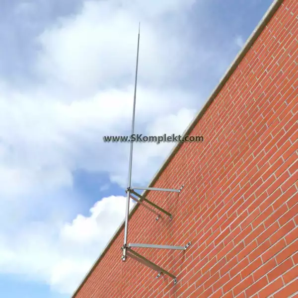
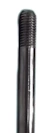
- установка 2 стержневых молниеприемников высотой 7,3 м на стене. Учтено, что 1,4 м длины стержня уходит на крепление;
- используется 4 стержневых молниеприемника высотой 7,3 м, установленные на АПК;
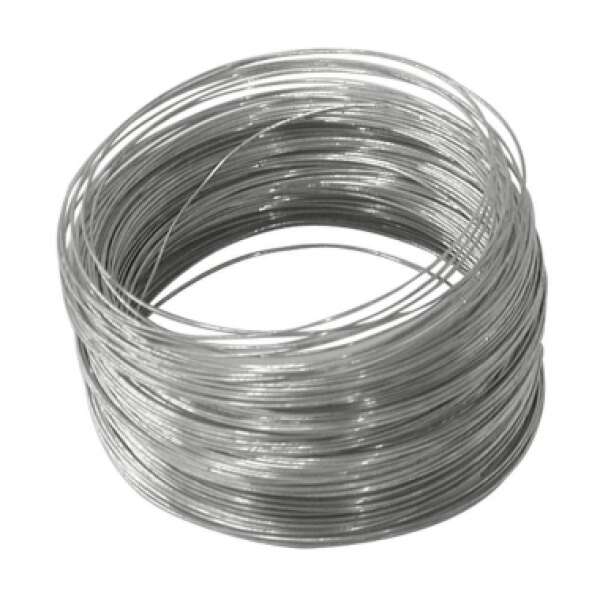
- молниеприемники соединяются между собой для организации двух токоотводов с применением оцинкованной проволоки D=8 мм от каждого молниеприемника;
- крепление токоотводов производится (шаг установки 0,6-1 м):
- на водосточном желобе с помощью зажимов ZZ-11545;
- на кровле и стене с помощью зажимов ZZ-11747;
- на водосточной трубе с помощью зажимов ZZ-11514;
- соединение и разветвление токоотводов производится с использованием зажимов ZZ-11551.
Комплекс мероприятий по обеспечению необходимых требований к заземляющему устройству представлен следующими решениями:
- монтаж заземляющего устройства, состоящего из горизонтального электрода (полоса оцинкованная стальная сечением 4x40 мм), глубина 0,5 м, расстояние до фундаментов 1 м и 4 вертикальных электродов (штырей из оцинкованной стали диаметром 16 мм) длиной 3 м;
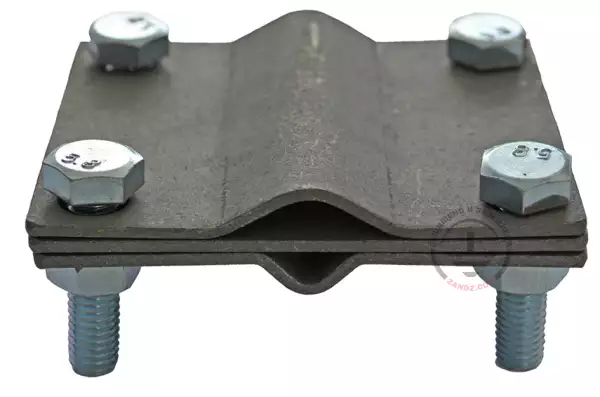
- соединение вертикальных и горизонтальных электродов между собой осуществляется с помощью зажимов ZZ-202-022;
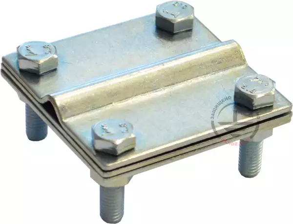
- соединение токоотвода с выводом оцинкованной полосы из земли осуществляется с помощью зажимов ZZ-202-023;
- конструкция заземляющего устройства соответствует пункту 1.7.55 ПУЭ. Заземляющие устройства защитного заземления и заземления для молниезащиты выполняются общими.
Расположение элементов системы молниезащиты и заземляющего устройства показано на чертеже в отдельном файле. Изображенная зона защиты соответствует надежности 0,9 СО.
Расчет сопротивления заземляющего устройства
Информация о типе грунта и его удельном сопротивлении заказчиком не предоставлена. Расчетное удельное сопротивление грунта принимается равным 100 Ом∙м.
Предупреждение. В случае ошибочности и ограниченности предоставленных заказчиком данных о грунте приведённый расчёт заземляющего устройства считается неверным. В случае отличия удельного сопротивления грунта от расчетного необходимо выполнить расчет с действительным значением. При превышении нормируемого сопротивления заземляющего устройства необходимо внести изменения в конструкцию.
Сопротивление горизонтального электрода:
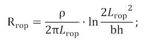
где ρ — удельное сопротивление грунта, Ом·м;
b — ширина полосы горизонтального электрода, м;
h — глубина заложения горизонтального электрода, м;
Lгор — длина горизонтального электрода, м.
Сопротивление вертикального электрода
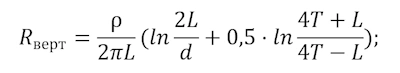
где ρ — удельное сопротивление грунта, Ом·м;
L — длина вертикального электрода, м;
d — диаметр вертикального электрода, м;
T — заглубление - расстояние от поверхности земли до заземлителя, м;
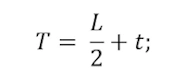
где t — заглубление верха электрода, м
Полное сопротивление заземляющего устройства:
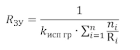
где n — количество комплектов;
kисп – коэффициент использования;
Рассчитывается сопротивление общего заземляющего устройства для АПК и ГЭС.
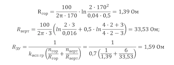
Расчетное сопротивление заземляющего устройства составляет 1,59 Ом.
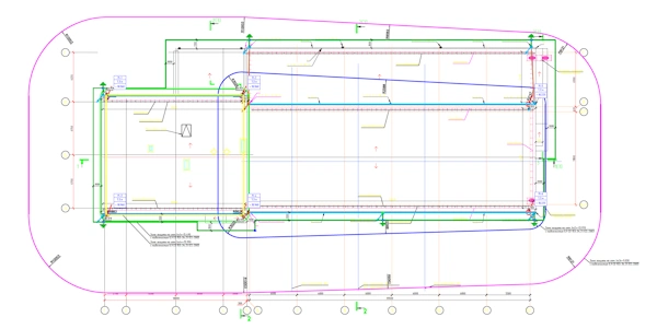
Смотрите план молниезащиты и узлы крепления на отдельной странице.
Таблица 1 – Перечень потребности материалов для ГЭС


У вас возникли вопросы по молниезащите фильтрационной насосной станции и cклада ацетона или других объектов? Обращайтесь за помощью в Технический Центр ZANDZ!
Смотрите также:
 Важность правильной организации молниезащиты на объектах электроэнергетики
 Проблема электробезопасности человека в грозовой обстановке Э.М. Базелян
 Проект молниезащиты и заземления административного здания с многоярусной плоской кровлей
 Подземные коммуникации несут опасность при ударе молнии! Э. М. Базелян