The third webinar of the Grounding and lightning protection: issues and problems arising in the design series
Webinar text. Page 3
Quick navigation through slides:
1.What are SPD designed for
2. GOST R IEC 61643-12-2011
3. SPD as a security tool against lightning surges in extreme cases
4. Physical mechanism of lightning overvoltage - a resistive component
5. Physical mechanism of lightning overvoltages - EMF induced by the magnetic field of the lightning
6. Surge suppression devices
7. Electrical circuit layout
8. Spatial orientation of electric circuits
9. Safe transportation of lightning current into the soil
10. Scanning the magnetic field along the diagonal of the building
11. Disturbance generating current goes across the shield
12. Disturbance generating current goes outside the shield
13. SPD operating principle
14. Basic physics
15. Zones protecting electrical and electronic systems from secondary effects of lightning
16. Selecting SPDs for a particular electrical circuit
17. Main parameters of SPDs
18. Rated withstanding surge for different categories of surge
19. List of parameters to select surge protective devices
20. Calculating lightning pulse current going through SPDs
21. The problem of parallel operation of an SPD
Varistors or spark gaps
RU
Варистор или искровой разрядник?
Варистор
Оксидноцинковая шайба
- чувствителен к качеству напряжения
- подвержен старению
- наличие тока утечки
- низкая надежность
- необходимость разъединителя
- невысока цена
Узип на основе разрядника
Камера с автоматическим тушением дуги
- не реагирует на перекос фаз
- отсутствие старения
- нет тока утечки
- высокая надежность
- работа без разъединителя
- стоимость выше на 30-40%
Решает заказчик
EN
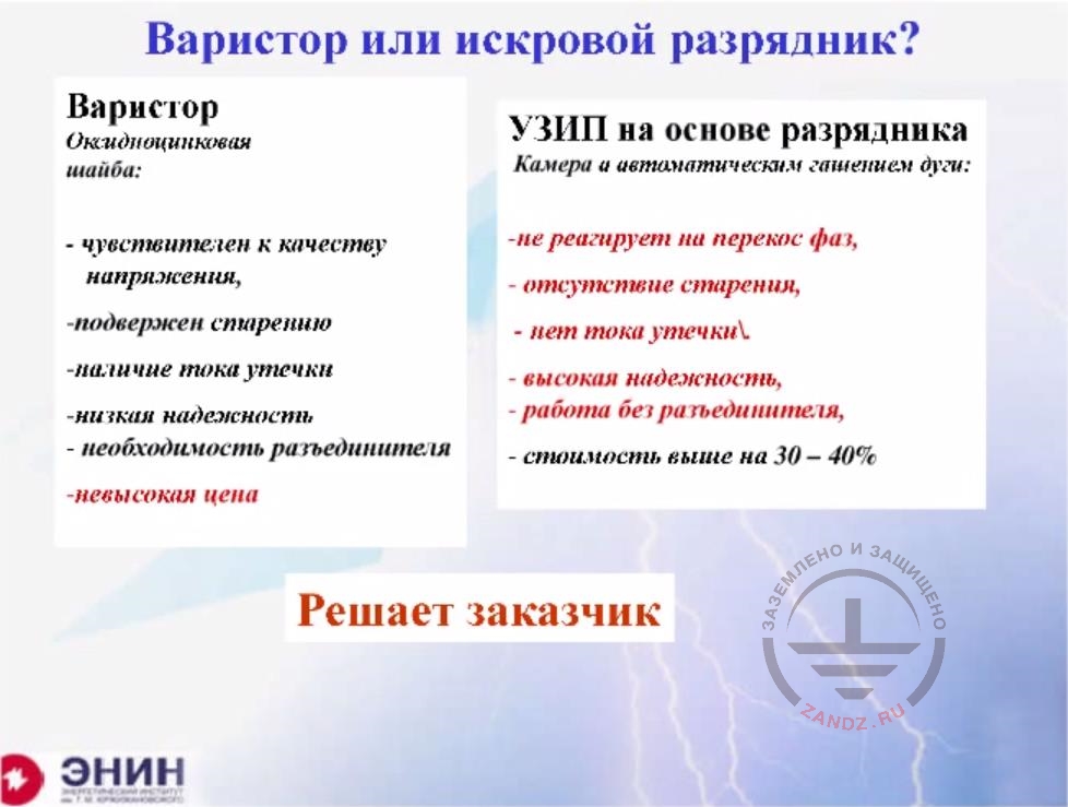
Varistors or spark gaps?
Varistor
Zinc oxide washer
- sensitive to voltage quality
- subject to ageing
- leakage current is present
- low reliability
- disconnect device is necessary
- low price
Spark gap SPD
Automatic arc extinguishing chamber
- does not sensible to phase distortions
- not subject to ageing
- high reliability
- high reliability
- no disconnect device is needed
- 30-40% more expensive
Client is to decide
Varistors are much cheaper and therefore many people want to install them. But what kind of trouble should you expect if you do that? Firstly, there can be a situation I have just described. When the current pulse drops, the current is moved from Class I varistor, and Class III varistor will burn. And the protected equipment will burn together with it. This is the first problem. The second problem is that the varistor is not sensitive enough to the voltage quality. If you have a phase shift and there's an increased voltage in the varistor, it may slightly open and overheat. The varistor is also subject to aging. There’s even a special line in varistor certificates — "varistor degradation ". And this degradation leads to the deterioration in performance of the varistor. It changes over time. Finally, if you use a sequence of varistors, then you need to put some protection device in case of a varistor failure. You need to install at least a fuse to disconnect the varistor. Spark gap-based SPDs do not have such a drawback, but they are considerably more expensive. Who can decide what to install? A varistor or an SPD?
Features SPD installation
RU
ГОСТ Р МЭК 61643-12-2011
Особенности монтажа
Обеспечение селективной работы
Недопустимо
Предпочтительно
Возможно
Индуктивность 1 м провода – 1 мкГн
При dImLdi=1011 A/c, UL =100 кВм!!!
Подавление паразитных колебаний
Хорошо, что через Узип проходит только малая часть тока
УЗИП
Разряд
EN
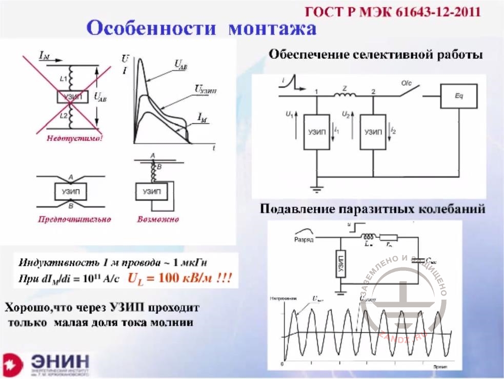
GOST R MEK 61643-12-2011
Features of installation
Providing selective operation
Inadmissible
Preferable
Possible
The inductance of 1 m of wire is 1 uHY
Under dIMLdi=1011 A/c, UL =100 kVm!!!
Parasitic oscillation suppression
It is good that only a small share of current goes through SPD
SPD
Discharge
A lot of attention is paid to the rules of SPD installation. Some companies even provide a sort of installer's training course to show what’ is necessary to do in order to mount the SPD correctly. I will not talk about all the intricacies of the installation, but I will definitely pay attention to a few things. The first thing is this: the SPD must be connected to the grid that it protects with wires of a minimum length. What is the minimum length? The inductance of the wire is the thing you should worry about in this case. The inductance of a conventional elongated wire is about 1 uH per one meter of length. Imagine a wire 1 meter long with an inductance of 1 mH. If you multiply the inductance by the lightning current speed, then you will get the surge. The calculated lightning current speed for Class III lightning protection facilities is 10 raised to a power of 11 A/s. If you multiply 10 raised to a power of 11 by an inductance of 10 raised to a power -6, you get 100,000 volts per one meter of wire. Therefore, this voltage is added to the residual voltage in the SPD. And to achieve the minimum voltage, you have to keep the length of the wire as small as possible. It should be no longer than about 0.5 meters. And even this value is too big. And very often it is recommended to make a V-shaped connector to the varistor to reduce the voltage drop across the wire induction to a minimum. This is absolutely necessary, and you have to do it. The second thing is that you have a voltage on the SPD. Let's assume this voltage is 1 kV, and you have electrical wiring downstream of the SPD, which is connected to appliances such as a computer. If you have a parasitic inductance in the wiring (and it is there for sure), then you also have a parasitic capacitance in any case. Normal oscillation can occur in the wiring, as in any RC loop. The amplitude of this oscillation doubles the voltage, so instead of 1 kV ensured by the SPD you will have twice as much of voltage on the contacts of you appliance. To avoid this, you should install a Class III SPD on the protection device of the last level, i.e. directly at the input of the protected equipment. Then there will be almost no parasitic oscillations. Finally, I've already said that it is necessary to ensure the selective operation of SPDs.
Features of SPD installation
RU
ГОСТ Р МЭК 61643-12-2011
Особенности монтажа
Разъединители УЗИП могут устанавливаться в цепи…
Для повышения уровня защиты соединительные проводники….
Р1
Р2-Р4
P5-P7
Р8-Р10
I ступень
II ступень
EN
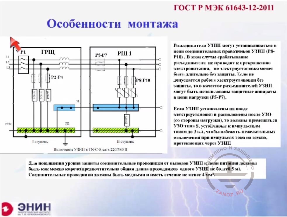
GOST R MEK 61643-12-2011
Features of installation
SPD disconnect devices can be installed in the SPD connection conductor circuits (P8-P10). In this case the tripping of disconnect devices does not lead to the power supply cut-off, but the electric installation can be left without protection for a long time. If this is unacceptable, then protection devices in the load circuit (P5-P7) can be used as SPD disconnect devices.
If SPDs are installed at the input of the electric installation downstream to the switchboard equipment, then S type switchboards resistant to a pulse up to 3 kA should be used to avoid undesirable disconnection in case is pulse currents goes to ground through the SPDs.
To increase the protection level, connection straps from SPD output terminals should be as short as possible (the total length of conductors for one SPD should be maximum 0.5 m). Copper connecting wires with a cross-section of at least 4 mm2 should be used.
Р1
Р2-Р4
P5-P7
Р8-Р10
Stage I
Stage II
What do we have in GOST dated 2011 I've mentioned before? There are clear rules of installation, and they are specified in this standard for absolutely all circuits. As an example, I've taken just one circuit most commonly used to power residential and public buildings in Russia. Here you have a four-wire system that enters the building, and then electric wiring is distributed inside the building via a five-wire system, as it is done today. In this case, it is very important to do the following. When you have a five-wire system, you install SPDs between the phase and the neutral wire and protect the neutral wire itself by connecting it to a central ground bus. This arrangement results in a minimum surge at the input of any single-phase device. There is also the following question: do you have to install devices to disconnect a damaged SPD. If your SPDs are varistor-based, you have to put such disconnect devices somewhere. Because sooner or later, your SPD will no longer work due to the degradation. They can be placed sequentially with SPDs, as it is shown in the picture to the left. In this case, after the fuse blows, the SPD turns off. The circuit remains in operation, but the protection of this circuit will not work and you have to inspect your fuses from time to time and look for the blown ones. If you put spark gaps directly in the fuse line, as shown in P5 and P7 to the right, then in case if the SPD is triggered, your relief will shut down. And if it is possible, then you will rush to turn it off. If this is impossible, then you'll still have to protect your SPDs with disconnect devices, which are here in the circuit, in P8 - P10. They will be triggered and disable SPD from the electric circuit. There's another important requirement. Protection tripping devices are often installed in homes. It is advisable to install SPDs before the PTDs, so that when an SPD has been activated no imbalance of current going through the PDT occurs, leading to its false operation.
SPD status monitoring
Контроль состояния УЗИП
Чаще на основе варисторов
Сигнализация о том, что УЗИП вышел из строя…
Простейшая ситуация – а при массовом использовании?
УЗИП
УЗИП серии BLITZDUCTOR RX
Прибор для тестирования УЗИП CHECKMASTER
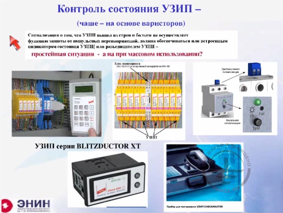
SPD status monitoring
Mostly varistor-based
The indication that an SPD is out of service and no longer provides protection from surge shall be performed by either by an integrated SPD status indicator or an SPD disconnect device -
This is the simplest situation, but what about mass installation?
SPD
BLITZDUCTOR RX series SPD
CHECKMASTER SPD testing device
I still want to spend at least 2 minutes to explain the following: you can always visually inspect those PTDs, for example in a cottage, when the household load increases. You can check if the fuse has blown. You can easily identify it with your hands. But sometimes SPDs are installed in dozens or even hundreds because of complex technical considerations. SPD status monitoring is a very important task. For this purpose, different companies use two fundamentally different methods. The first method is SPD monitoring tests. You must go to the cabinet, connect a tester and look at its display or indicator lamps. It shows if a particular SPD is functional or non-functional. The second method, which becomes more and more widespread is the Blitz Doctor series. It allows you to carry out inspection both visually and remotely. This remote visual inspection is carried out as follows: you will have a series of 10 SPDs, and you can connect 40 electric circuits to them. Each SPD protects four circuits at once. And additionally, there is an electronic unit which periodically monitors these SPDs. And a communication system transmits information to the control room. In the control room, you can see which of your SPDs are operational, which SPDs are to be replaced, and which are simply out of order. This monitoring system is suitable for up to 15,000 circuits. And in general, I do not think that anyone dares to use it in the residential construction, but this quite an expensive system is efficient at large process facilities. Do we have questions already?
- Hello, dear attendees, my name is Nadezhda. I'll help Edward and pass him your questions. I tried to write them down during the webinar, but if any of them still left you can ask them via the general chat. I'm going to read them for sure. We've got a number of questions and comments. There were some comments already, for example, that you cannot move all the cables away from the lightning rods and the ground electrode system at your facility. This is what we were talking about during the first part of our webinar.
- Of course, it is impossible. Moreover, it is technically impossible to do that in some situations. It is infeasible, and by saying you have to move them away I meant the following. I meant that before deciding whether or not you should install the SPDs, you must apply solutions that do not require altering the electrical circuit. If for example, the cable can be moved away from the lightning rod, it should be moved away. If the cable cannot be moved away from the lightning rod, and these situations occur very often, you have to use other means of protection. And these include SPDs. Of course, I agree with that. But if you make your wiring layout irrationally during the project design, and you know it is irrational, it is better to change this layout now than to remake your protection system afterward. That's what I was saying. More questions?
- There's a question about calculating the percentage of lightning current that will flow through the SPD. There were comments that this method of calculation you had mentioned referred to IEC 616 043 and 62 305 respectively, not to a specific company. This means this is IEC method.
- The thing is this. Do not get me wrong. It means that if you have a facility with outgoing communications, then you can calculate the current for the SPD of a particular electrical circuit with consideration of all these communications. Just tell me, please, who told you that you have the current evenly distributed throughout the communications? Who told you that, for example, the same share of current will come to the water pipeline and the power mains? What is that?! What's this? An evidence-based result? Or is it a guess work? This a guess work, because in reality the current will be distributed over the resistance wave patterns of the underground cable on the one hand and the surge impedance on the other. And these are different resistances. Therefore, this methodical evaluation, although it is set forth in the GOST, can lead to an error in the tens or even more percent. That's what I would like to draw your attention to. And there's another thing. What will you take for the design case? If you take a lightning strike into the building as the design case this would be one situation. And if you take a lightning strike to an incoming power line as the design case, then this would be a different situation. And the number of strikes into the incoming line will surely be greater than the number of strikes into the building. Especially if it is a single-family house. But if you have, for example, a multi-story building and your incoming power line is an underground cable, then it is not necessary to take into account the overhead line because the currents do not branch off.
- And there's a question about the distance between SPDs of different classes, which is required when there are several of them. One of our attendees is asking to clarify that again, as there were questions there. What distance between the SPDs should be maintained?
- There are things to do. You have two SPDs. The first SPD is installed at the Class I input, the second one is installed downstream, closer to the load. You need the first SPD to be activated and pass the current thought itself, and the second SPD to take the remainder of the current upon itself. This is what you need to do. It is necessary to harmonize the SPDs. To do this, it is necessary that the voltage comes into the first SPD earlier than into the second SPD. How can you do that? This can be done by arranging for a voltage transmission delay. This delay can be achieved either using a long conductor because the voltage wave moves along the conductor at a speed of 300 m per microsecond. Alternatively, you can switch on the inductance, which will cause the voltage drop and block the front of this impulse. You can apply either of the options. Many firms specify what choke you should install, or how much uH you need to switch on to achieve the result. Alternatively, they specify the length of a conductor, because both solutions work. An average figure for the conductor length specified by such firms is approximately 10 meters or 10 to 15 uH for a choke to be included in this circuit.
- And the last question is: could you provide a specific example of the choice of the SPD. Maybe not in the format of the webinar, but in general. There was also a question in the beginning of the seminar: are you going to write your own guidance.
- So, we are through for today. There is another question we've discussed during our last webinar, and this is software. How does this statistical method relate to SO and RD standards?
- What should I say? We've handed over the software to ZANDZ.com project. This company is now working to migrate this software to the cloud. The question is when will it be ready? They told me the following. We are not going to set this back for too long. For my part, I will ask the company to explain when it intends to proceed with this work.
I'd like to ask the following, dear attendees. I am very much concerned about the grounding. And I would like to devote our next seminar solely to processes occurring in the soil. Nothing else but processes in the soil. How to calculate the grounding? What are the right solutions and what are not? How to evaluate electrodes from different manufacturers? But without naming specific companies again. I would like to host such a seminar. If you don't mind, then we will meet in a month and hold the seminar.
- And there's another question about SPDs. There are SPDs that combine Class I and II protection. Is this the right solution?
- Thank you for this question. I wanted to tell you about it, but unfortunately, I didn't have enough time. Class I+II SPD are available in large assortment today. Such SPDs are based on spark gaps with automatic arc extinguishing. There are also Class I+II SPDs made on the basis of varistors. By their by throughput, such SPDs correspond to Class I, so they pass a current of 10 kA, or approximately up to 12.5 kA. As for residual voltage, it corresponds to Class II and the voltage at its terminals is around 2.5 kV. This is a very high-quality and very handy component that solves almost all problems except one. One problem remains unsolved. Let's assume you've installed a Class I+II SPD, so you no longer need Class II and you can lay your circuit directly to the device you want to protect. For example, your computer. If your computer is plugged into the mains, you will install Class III SPD on the computer input. You do that in order to reduce the voltage at the input of the computer below the value the computer power unit is designed for. And now you have one question left - how to harmonize Class III SPD and the I+II devise. The issue of coordination needs to be solved. And this is the same question I was talking about. By laying a line 10 meters long or including some kind of a specialized actuating device, you will achieve the SPDs' selective tripping. And this should be done for sure. As for the future behavior of this couple, you need to know some nuances. If you SPD Class I+II is varistor-based, then all will work fine until the lightning current pulse drops to a small value. What is the small value? For example, it was 12.5 kA and then dropped to only 500 A. In this case, the current-voltage curve of Class III SPDs can overlap with the current-voltage curve of the Class I varistor. And the Class III SPD can burn down. For this reason, please be cautious to use cheap Class I+II SPDs, if they are varistor-based. Class I+II SPDs based on spark gaps will never allow such overlap. They are simply more reliable, but they are also more expensive.
- So we are through for today basically. Dear attendees, please complete our evaluation questionnaire. I'm publishing a link to the questionnaire in the general chat. I'd like to get your feedback. You can write in more detail, what you liked or did not like, and what improvements do you expect. Now, as for the next webinar.
Thank you very much for your attention, and excuse me for the mouse pointer, which isn't moving.
I'd like to say that all participants agree that the next webinar will be devoted to grounding. They are ready and looking forward to the next webinar.
Thanks a lot! See you next time!
Do you have any questions left? Send them to our technicians and you will receive detailed and reasoned answers.
<< Previous Page
Slides 11 to 21
Useful materials for designers:
- Webinars with the leading industry experts
- Everything for the grounding and lightning protection calculation
- Useful materials: articles, recommendations, examples
Related Articles:
