Task
Facility: intermediate point of selective railroad communication, with a communication box.
The specific soil resistivity: 150 Ohm·m.
The calculations and the design of the protective grounding circuit are required. In accordance with paragraph 2.1.1 of GOST 464-79, it is required to generate a protective grounding device and two measuring grounding devices. In paragraphs 1.7, 2.1.3 of GOST 464-79 it is specified that the resistance of the protective grounding device should not exceed 30 Ohms, and the resistance of the measuring grounding device should not exceed 200 Ohms for the soils with the specific resistivity of not more than 100 Ohm·m.
Solution
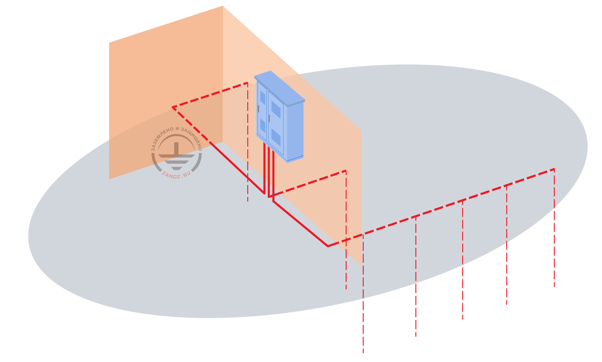
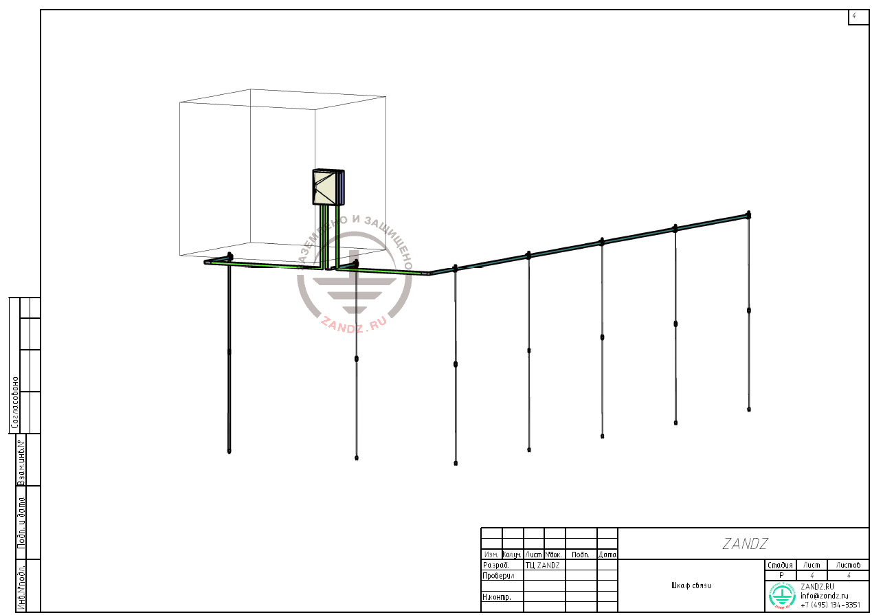
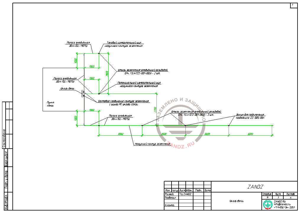
The design contains technical solutions regarding the arrangement of the grounding circuit for the communication box. The grounding circuit is intended for providing normal operation of the equipment located in the communication box and allows reducing the external interference impact on the equipment. According to the calculation data, the grounding circuit is made of five vertical electrodes (copper-bonded threaded rods D14, 1.5 m ZZ-001-065, 2 pieces per 1 electrode) and copper-bonded tape 30 x 4 GL-11075 connected with the clamp for connecting conductor ZZ-005-064 (see full specification and links to the description of equipment below).
The current and potential measuring grounding devices are made of one vertical electrode (copper-bonded threaded rods D14, 1.5 m ZZ-001-065, 2 pieces per 1 electrode) and copper-bonded tape 30 x 4 GL-11075 connected with the clamp for connecting conductor ZZ-005-064 (see full specification and links to the description of equipment below).
In order to control the ends of connection of grounding devices with the grounding conductors and to perform control measurements of the grounding device resistance, the installation of inspection wells is provided (GL-11402). External grounding circuit and measuring probes are connected with the PE bus of the communication box using the copper-bonded tape 30 x 4 (GL-11075).
Carry out waterproofing for bolt connections and allow for inspecting connections at any time. The grounding device (grounding circuit) is laid at the depth of 0.5 m from the ground surface at the distance of 1 m from the communication point. For arrangement of the external grounding circuit, see drawings of this design.
Carry out installation of the grounding circuit according to EIC, ed. 7, GOST 464-79 "Grounding for Stationary Installations of Wire Communication, Radio Relay Stations, Broadcasting Units and Antennas for Community TV Reception Systems. Standards for Resistance, Manuals for Design, Construction, and Operation of Grounding Devices in the Installations of Wire Communication and Broadcasting Units".
The resistance calculation for the grounding device:
The calculation of the grounding circuit is carried out in accordance with the Manual for Design, Construction, and Operation of Grounding Devices in the Installations of Wire Communication and Broadcasting Units.
The design soil resistivity is taken as follows:
Pрасч is 150 Оhm·m;
Freezing factor:
for vertical grounding device — 1.8;
for horizontal grounding device — 4.5;
nв = 0.66 (utilization ratio from Table 2.5, see Manual);
nг = 0.40 (utilization ratio from Table 2.8, see Manual).
Distance between electrodes — L of a vertical grounding device.
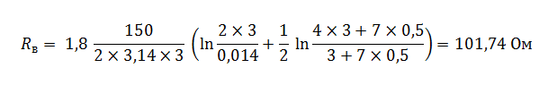
Vertical electrode resistance:
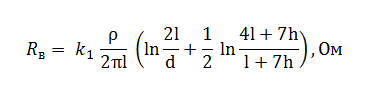
where L is the vertical grounding device length, m;
d is the external diameter of the vertical grounding device, m;
h is the distance from the ground surface to the upper end of the vertical grounding device, m;
ρ is the specific soil resistivity, Ohm·m;
k1 is the freezing factor considering seasonal temperature variations of the soil.
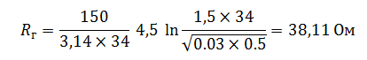
Horizontal electrode resistance:
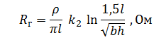
where L is the grounding device length, m;
b is the band width, m;
h is the depth of the band laying, m;
ρ is the specific soil resistivity, Ohm·m;
k2 is the freezing ratio considering the seasonal temperature variations of the soil.
The design resistance of the multi-electrode grounding device:
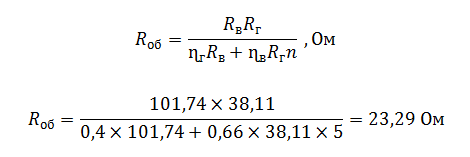
The design resistance of the grounding device is 23.29 Ohms, which is less than the permissible resistance of 30 Ohms.
The measuring probe resistance:
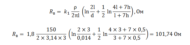
The design resistance of the measuring grounding device is 101.74 Ohms, which is less than the permissible resistance of 200 Ohms.
The list of required materials:
| № | Fig. | Product item | Name | Quantity | Weight, unit, kg |
| 1. |  |
ZZ-001-065 | ZANDZ Copper-bonded threaded grounding rod (D14; 1.5 m) | 14 | 1,9 |
| 2. |  |
ZZ-002-061 | ZANDZ Threaded coupler | 7 | 0,08 |
| 3. |  |
GL-11703A | ZANDZ Starting tip | 7 | 0,07 |
| 4. |  |
ZZ-004-060 | ZANDZ Driving head for jackhammer | 4 | 0,09 |
| 5. |  |
ZZ-005-064 | ZANDZ Clamp for connecting conductor (up to 40 mm) | 7 | 0,31 |
| 6. |  |
ZZ-006-000 | ZANDZ Conductive grease | 3 | 0,19 |
| 7. |  |
ZZ-007-030 | ZANDZ Waterproof tape | 3 | 0,442 |
| 8. |  |
ZZ-008-000 | ZANDZ Head for jackhammer (SDS max) | 1 | 0,48 |
| 9. |  |
GL-11402 | GALMAR Inspection well | 7 | 2,6 |
| 10. |  |
GL-11075 | GALMAR Copper-bonded tape 30 x 4 mm | 34 | 0.98 (in meters) |
Appendix: design is available in DWG and PDF formats
Do you need to design the grounding and lightning protection system? Order it by contacting the ZANDZ Technical Centre.
Related Articles:
 Lightning Protection Design for a Railroad Terminal and Station
