Task:
It is necessary to make calculations and make a grounding and lighting protection project for the object. Grounding resistance should not be more than 10 Ohm (protection against static electricity)
Diameter of the tank:12,33 m, height: 10,67 m, height of the breathing valves 0,3 m
Soil resistivity - 150 Ohm * m;
The tanks have conic shell.
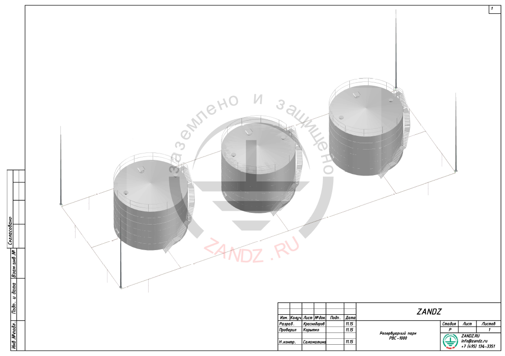
Download the layout of oil tanks in PDF.
Download the layout of oil tanks in DWG (AutoCAD).
Solution:
The calculations were performed in accordance with the EIC 7th ed., IS 153-34.21.122-2003 "Instructions for lightning protection of buildings, structures, and industrial communications" (hereinafter IS) and AD 34.21.122-87 "Instruction for lightning protection of buildings and structures" (hereinafter AD).
This reservoire park refers to category III б in accordance with SNiP 2.11.03-63 "Oil and oil prodicts warehouses. Fire protection standards".
The II level of protection from direct lightning strike and category of protection 0,95, as oil is highly-flammable liquid are chosen for a warehouse of oil and oil products of category III in accordance with the indistry standard SA-03-002-2009 "Rules of design, manufacture and installation of vertical cylindrical steel tanks for oil and oil products".
For II protection level, direct lightning strikes protection must be carried out by free-standing lightning rods.
In accordance with p.2.6 AD the protection zone should contain a space, limited by the cylinder 2,5 m high and 5 meters in radius over the breething valves (p.2.18).
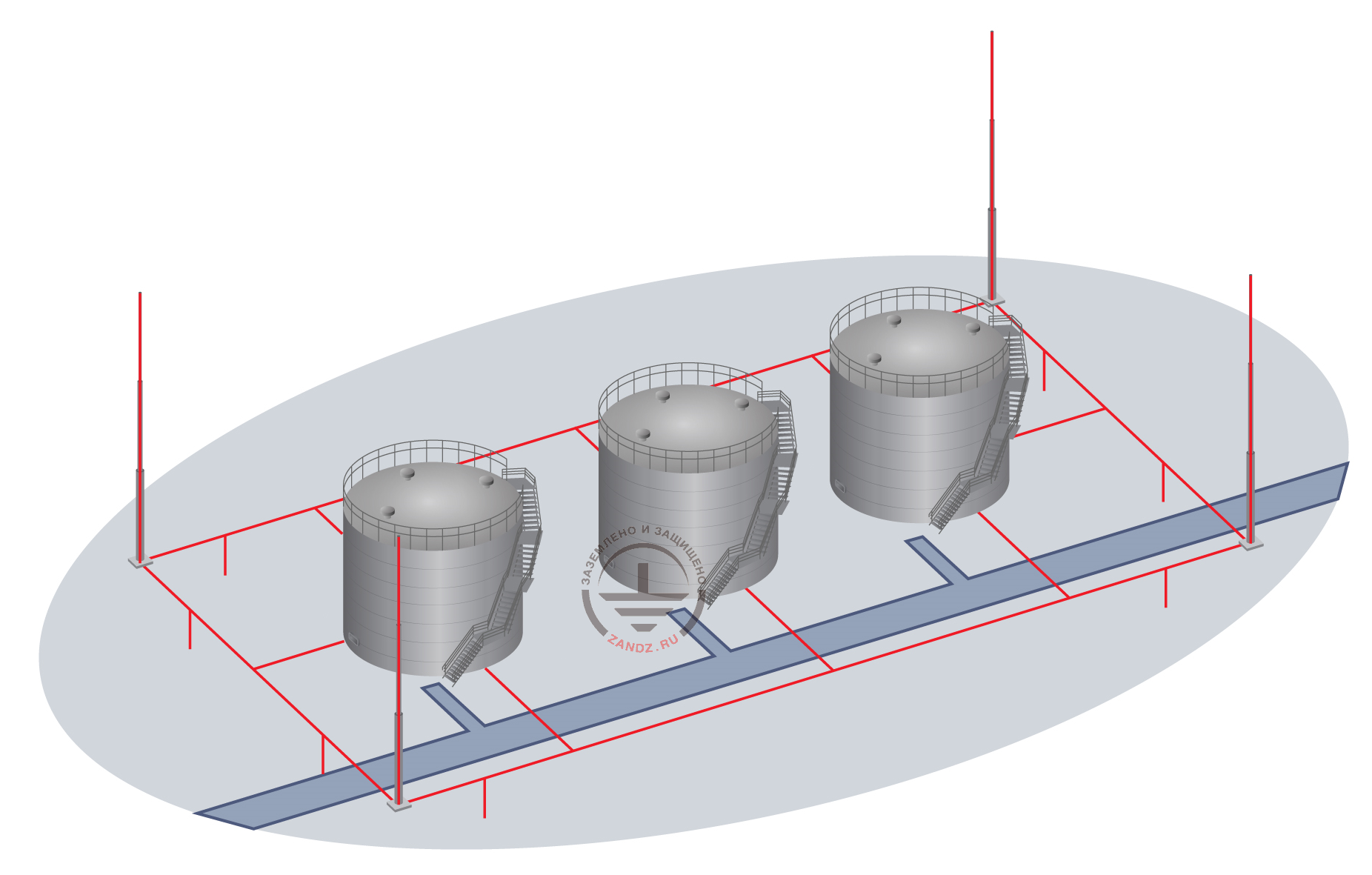
Lightning protection of the tank partk is carried out by 4 free standing lightning rods 18 m high. The current spreading in two directions along the horizontal electrodes of the grounding device is carried out from each lightning rod. One vertical electrode 3 m long is installed in every direction at the distance of 5 m. The down conductor from the lightning rod is connected to the grounding device with the help of the clamp for connecting grounding conductor ZZ-005-064.
"Rules of technical use of tanks of magistral oil pipes and oil tank farms" AD 153-39.4-078-01 pose the following requirements regarding the grounding devices of the tanks:
5.1.4 It is necessary to use artificial ground electrodes, laid in the ground and placed not closer than 50 m along the perimeter of the tank base, to which the body of the tank must be connected (number of connections - not less than 2 in polar opposite points as ground electrodes to protect the tanks from direct lightning strikes.
5.1.9. In the presence of rod and catenary wire lightning rods, each down conductor is connected to the artificial ground electrode, consisting of 3 and more vertical electrodes not less than 3 m long, united by the horizontal electrode, at the distance between the vertical electrodes not less than 5 m. Down conductors and ground electrodes are chosen in accordance with the requirements of the active normative and technical documentation.
Grounding device is carried out by the following method:
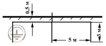
- Contour of horizontal electrodes is made - copper-bonded tape 30x4 mm, the depth of laying - 0,5 m. Each reservoir is connected to the common contour not less than in two points.
- Use copper-bonded tape 30x4 mm as the grounding conductor, which is connected to the bottom part of the reservoir wall with the help of a clamp for connecting grounding conductor ZZ-005-064 (see figures 2,3). The distance from the horizontal contour to the reservoir wall 5 m.
- Arrangement of horizontal and vertical electrodes is shown in Figure 1 and on the drawing. The order of installation of modular grounding is given at the final pages.
The results of lightning protection calculation performed by the software, developed by JSC "Energy Institute to the name of Krzhizhanovsky "(JSC" ENIN ") are presented in table 1.
The following source data were taken for the calculation: density of lightning strikes into the ground - 4 strikes / sq. km per year; number of strikes into an unprotected object - 0,045/year, period - once in 22 years.
| № | Object | Height of a lightning rod, m | Protection reliability | The number of strikes into an object, 1/year | The number of breakthroughs into the object, 1/year |
| Period of srikes, year | Period of breakthroughs, year | ||||
| 1 | Tank farm | 18 | 0,975 | 0,08 | 0,002 |
| once in 12,5 years | once in 500 years |
Chart 1. Lightning protection calculation
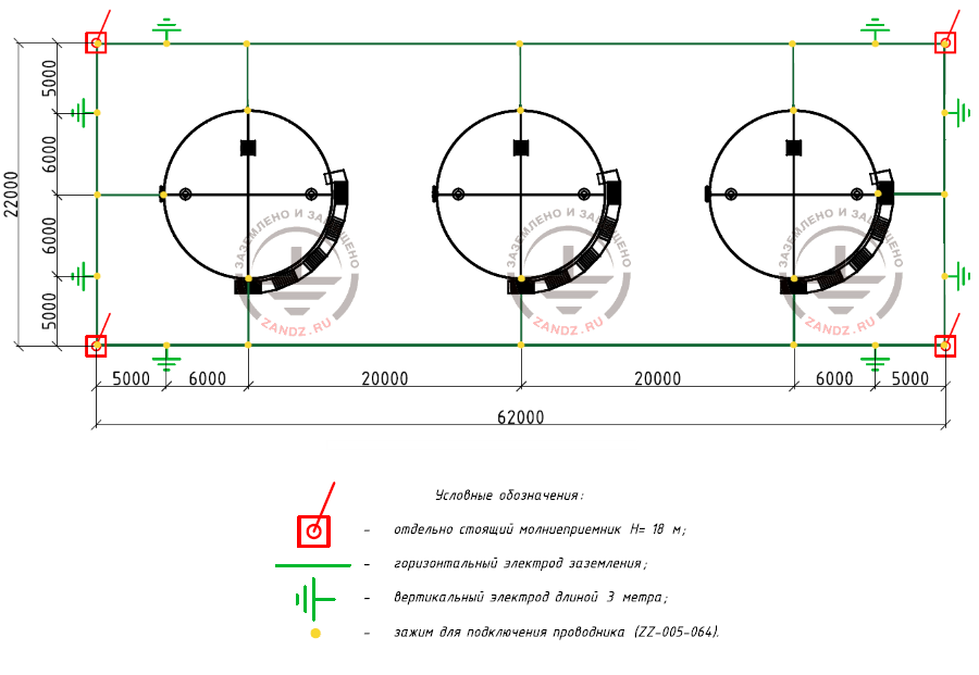
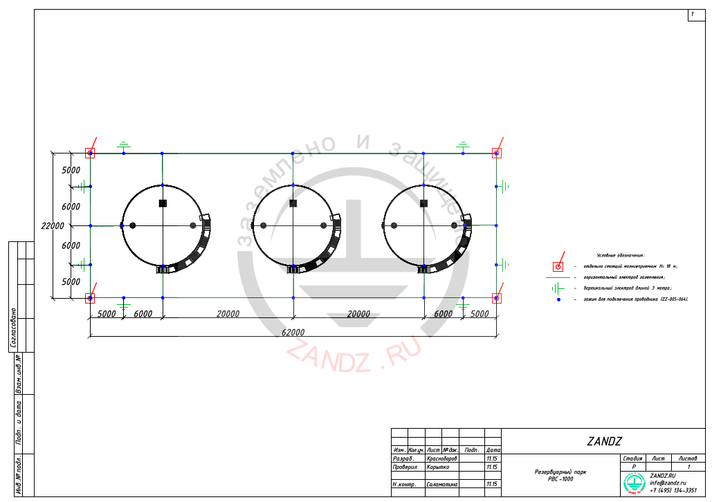
Figure 1 – Lightning protection and grounding elements layout
Условные обозначения – code designation
Отдельно стоящий молниеприемник – free standing lightning rod
Горизонтальный электрод заземления – horizontal ground electrode
Вертикальный электрод длиной 3 метра – vertical electrode 3 m long
Зажим для подключения проводника – clamp for connecting conductor
Calculation of grounding device resistance:
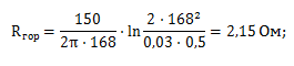
Resistance of a horizontal electrode:
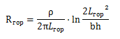
ρ - soil resistivity, Ohm* m; b - horizontal electrode tape width ,m; Lгор - horizontal electrode length, m.
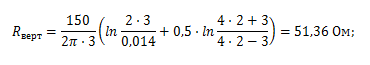
Resistance of a vertical electrode:
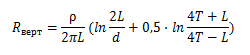
where ρ - equivalent soil resistivity, ohm · m;
L - length of the vertical electrode, m;
d - vertical electrode diameter, m;
T- deepening - distance from the ground surface to the ground electrode, m;
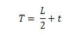
where t - deepening of the electrode top, m
Impedance of the grounding device:
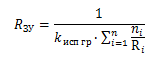
where n - number of kits; Kисп - utilization ratio;

The design resistance of the grounding device is 2.24 ohms.
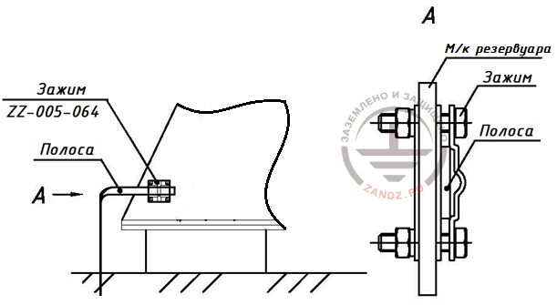
Figure 2 - Installation of a clamp for metal structures of the tank
Зажим - clamp
Полоса - tape
м\к резервуара – tank metal structure
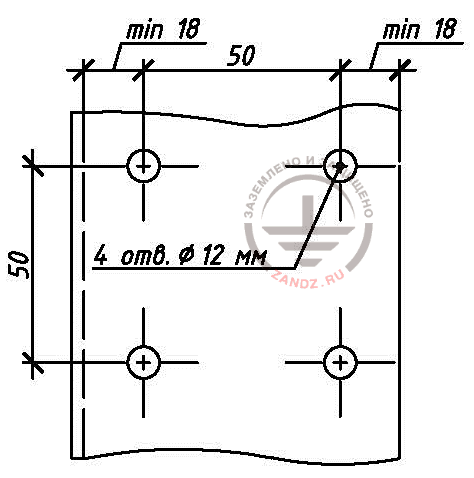
Figure 3- Marking of holes for the clamp
The list of required materials:
| № | Fig | Product item | Product | Q-ty |
| 1 | 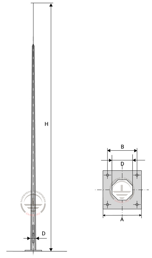 |
ZZ-201-018 | ZANDZ Vertical lightning rod 18m (galvanized steel;. with embedded details under the foundation) | 4 |
| 2 | 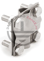 |
ZZ-005-064 | ZANDZ Clamp for connecting conductor (up to 40 mm) | 32 |
| 3 | 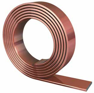 |
GL-11075-50 | GALMAR Copper-bonded tape (30 * 4 mm / S 120 mm²; coil 50 meters) | 3 |
| 4 | |
GL-11075-20 | GALMAR copper-bonded tape (30 * 4 mm / S 120 mm²; coil of 20 meters) | 1 |
| 5 | 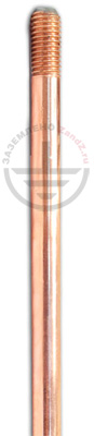 |
ZZ-001-065 | ZANDZ Copper-bonded threaded grounding rod (D14; 1,5 m) | 16 |
| 6 | 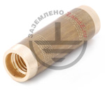 |
ZZ-002-061 | ZANDZ Threaded coupler | 9 |
| 7 | 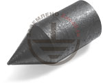 |
ZZ-003-061 | ZANDZ Starting tip | 8 |
| 8 |  |
ZZ-004-060 | ZANDZ Driving head for a breaker hammer | 4 |
| 9 |  |
ZZ-006-000 | ZANDZ Conductive grease | 1 |
| 10 |  |
ZZ-007-030 | ZANDZ Water-proof tape | 3 |
| 11 |  |
ZZ-008-000 | ZANDZ Cap for a breaker hammer (SDS max) | 1 |
Appendix: the project is available in DWG and PDF formats
Files in the formats DWG and PDF are available for downloading only for authorized users.
Do you need to make the project on grounding and lightning protection? Order it by contacting the ZANDZ.ru Technical Center!
Any more questions on the calculation left? Ask them in the comments to this page!
Related Articles:
 Lightning protection resistance
 Lightning Protection and Grounding of Oil Reservoirs. Review of Guidelines for Oil Plant and Warehouse Safety