Task:
Object: data processing center (DPC), located in a separate building.
Soil: sand clay
Soil resisitivity: 150 Ohm*m
Solution:
The activities were carried out in accordance with the TIA 942, IEC 24764 and EIC 7 th ed. Chapter 1.7.
In accordance with TIA 942, no part of grounding systems should not have resistance more than 5 Ohm regarding the ground itself.
The set of measures to ensure the necessary requirements to the grounding device is represented by the following solutions:
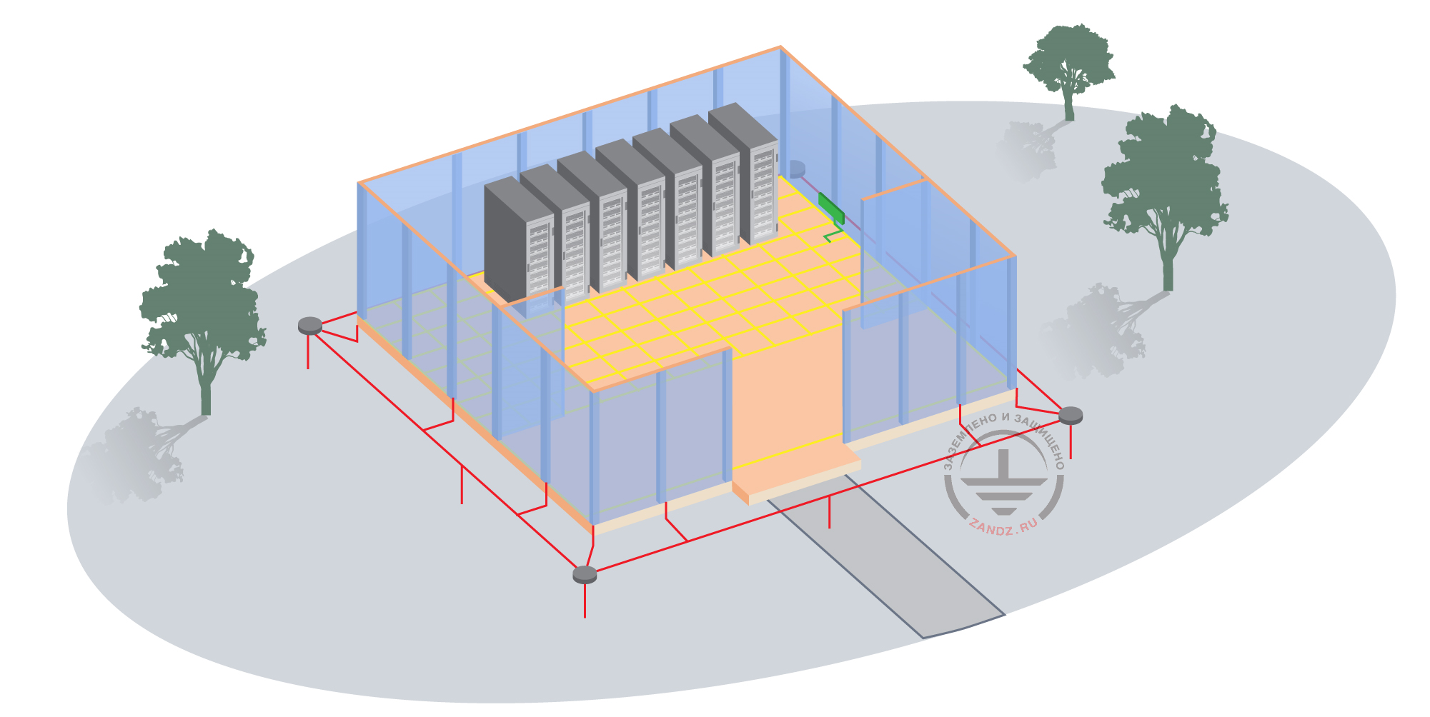
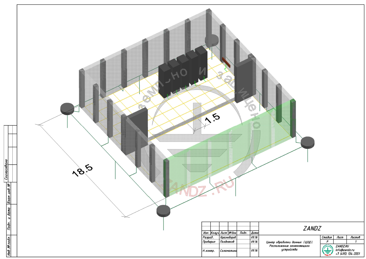
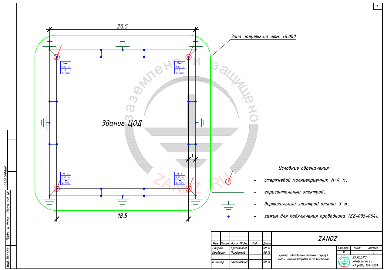
- Installation of the horizontal contour with the dimensions of 20,5 x 20,5 m around the building. The horizontal ground electrode is carried out of copper-bonded tape with the cross-section of 4x30 at the depth of 1 m, distance from the wall 1 m.
- Installation of 8 vertical electrodes of copper-bonded steel 3 m long and diameter of 14 mm is carried out along the whole grounding contour length.
- Inspection pits are provided at 4 corners of the grounding contour.
- Steel structures of the building are connected with the grounding contour at every second column with the help of the copper-bonded tape with the cross-section.
- The grounding resistance of any part of the system may not exceed 5 Ohm.
- Large equipment distributing power, telecommunication and lightning protection systems must be connected to the grounding system.
- The buses must be available for connection and visual inspection.
- If data-center is located in the region with good soil (like clay, sand clay, clay loam) with the resisitivity of 60-150 Ohm*m, soil resistance up to 5 Ohm can be achieved by the measures mentioned above. It is necessary to make calculation of grounding in case of exceeding, take additional measures.
- If the soil is permafrost with the resistance 1000 Ohm*m and more, special measures on the reduction of ground resistance, for example, installation of ZANDZ electrolytic kits is required.
- If the equipment installed requires ground resistance lower than 5 Ohm, for example 1 Ohm, then electrolytic grounding kits can be also installed to achieve these indexes.
Equipotential bonding measures:
-
Equipotential grounding mesh of a copper insulated conductor with the cross-section of 25 mm2, covering the whole area of the machine room, is laid in the floor of the machine room of the data center. The size of the mesh cell is 1,5 m. The insulation is taken off in the nods of intersection and connection of conductors. The mesh creates equipotential basis and reduces high-frequency parasite sygnals (reduces disturbances).
-
The elements of the data center listed below are connected to the equipotential mesh of conductors:
-
telecommunication grounding bus in the machine room by the ground conductor, the cross section of which is 25 mm2;
-
in each service room, a distribution device or board are connected with the grounding bus by the ground conductor. The cross-section is chosen according to the operative current of the switching device by NEC 250.122;
-
HVAC equipment (heating, ventilation, conditioning) by the ground conductor with the cross-section 16 mm2;
-
each column in the machine room by the grounding conductor, the cross section of which is 25 mm2;
-
each elevated cable ladder, cable tray and gutter for laying the cable, entering the room by the ground conductor, the cross-section of which is 16 mm2;
-
each cable passage, water pipe and air pipe by the ground conductor with the cross-section 16 mm2;
-
each sixth support of the hollow floor in each direction by the ground conductor with the cross-section 16 mm2;
-
each computer or telecommunication board, rack panel and frame by the ground conductor, the cross-section of which is 16 mm2. Each element of the board or rack panel construction must be grounded - electrical continuity must be provided.
-
-
A copper rod or tape, which will be an appropriate point of connecting the ground conductor are connected to each rack. Equipment chassis must be connected with the rack panel. Connection to the rack panel must have the following features:
-
pure contact metal-metal;
-
recommended antioxidant.
-
-
Ground conductors must be not longer than 0,5m and must have copper tips on both sides for connecting to the elements of the data-center and to equipotential mesh conductors.
Calculation of lightning protection:
The following source data are taken for the calculation:
- density of lightning strikes into the ground - 4 strikes / sq. km per year;
- number of strikes into an unprotected object - 0.011 1/year, period - once in 90 years.
The results of lightning protection calculation performed by the software, developed by JSC "Energy Institute to the name of Krzhizhanovsky "(JSC" ENIN ") are presented in table 1.
Table 1 - Results of lightning protection calculation
| № | Object | Lightning rod height, m | Protection reliability | Number of strikes per year-1 | Number of breakthroughs per year-1 |
| Period of srikes, year | Period of breakthroughs, year | ||||
| 1 | Data Center | 4 | 0,99983 | 0,019 | 0,0000032 |
| once in 52 years | once in 312500 years |
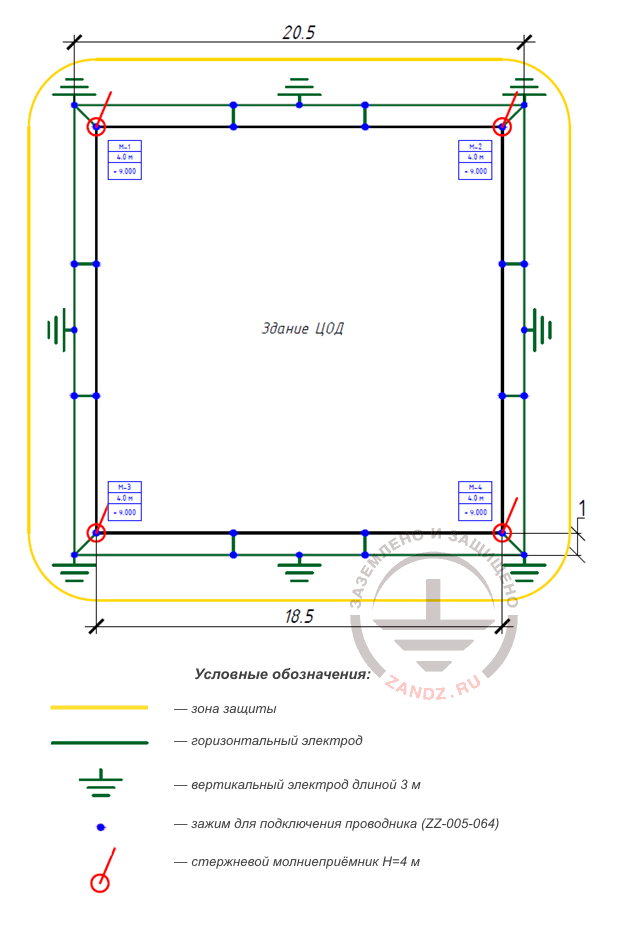
Figure 1 - grounding and lightning protection device elements layout
Условные обозначения – code designations
Зона защиты – protection zone
Горизонтальный электрод – horizontal electrode
Вертикальный электрод длиной 3 м – vertical electrode 3 m long
Зажим для подключения проводника – clamp for connecting conductor
Стержневой молниеприемник – rod lightning rod
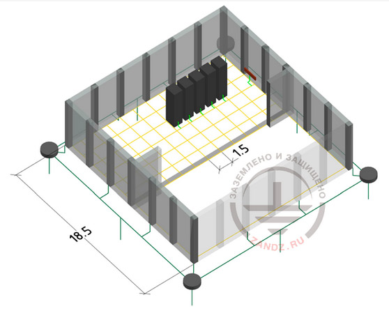
Figure 2 - grounding device elements layout
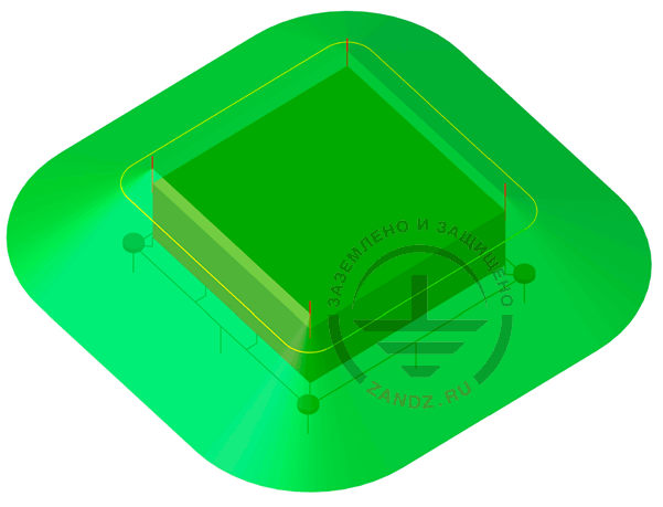
Figure 3 - Arrangement of lightning protection elements and protection zone
Calculation of a grounding device
In accordance with the
Lightning protection is calculated using the software developed by JSC "Energy Institute to the name of G. M. Krzizhanovsky" (JSC "ENIN").
Specific soil resistance of clay loam is taken equal to 100 Ohm ∙ m.
Horizontal electrode resistance:
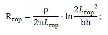
ρ- soil resistivity, Ohm* m;
b - horizontal electrode tape width, m;
h - depth of horizontal mesh laying, m
Lгор - horizontal electrode length, m.
Vertical electrode resistance:
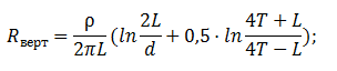
where ρ - equivalent soil resistivity, ohm · m; L - length of the vertical electrode, m; d - vertical electrode diameter, m; T- deepening - distance from the ground surface to the ground electrode, m;
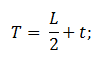
where t - deepening of the electrode top, m
Impedance of the grounding device:
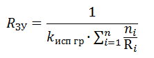
where n - number of kits;
Kисп - utilization ratio;
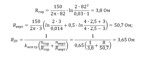
The design resistance of the grounding device is 3.65 ohms, which is less than the required value of 5 ohms.
Internal lightning protection (overvoltage protection):
-
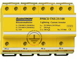
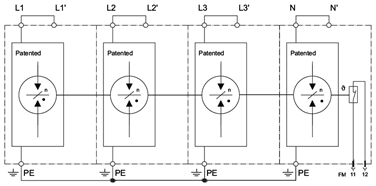
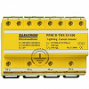
To protect mains circuits with the voltahe 0,4 kW, three-phase SPDs of class 1+2+3 PowerPro BCD TNS are installed at every power input from the transformer substation and reserve source of power supply.
-
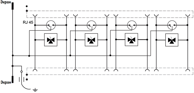
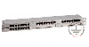
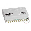
To protect Ethernet data transmission circuits, SPD DataPro X8RJ45-19", is mounted to protect the twisted paid RJ45.

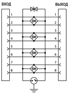
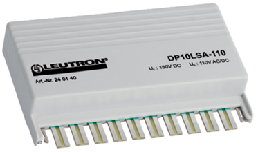
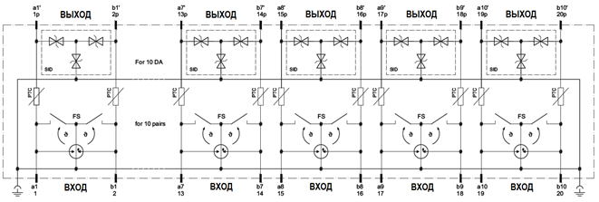
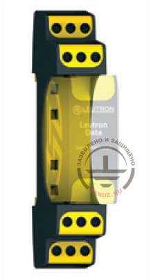
DataPro 10LSA (PTC) is mounted to protect the lines in LSA modules.
-
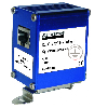
To protect IP camera with POE technology, SPD DataPro RJ45 PoE Alu is installed, from the side of the switch panel SPD DataPro x8RJ45-19" can be installed.

-
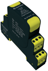
Protection of equipment in automation, management and control networks is carried out with the help of SPD MP 2x2 GDT +12V-Ad-Ad-Pg ST and MP 2x2 GDT +24V-Ad-Ad-Pg ST in 12 W and 24 W circuits correspondingly, which are installed into MP Base 2x2-R GDT, and also with the help of DataPro x8RJ45-19".
The list of required materials:


Appendix: the project is available in DWG and PDF formats
Do you need to make the project on grounding and lightning protection? Order it by contacting the ZANDZ Technical Center!
Related Articles:
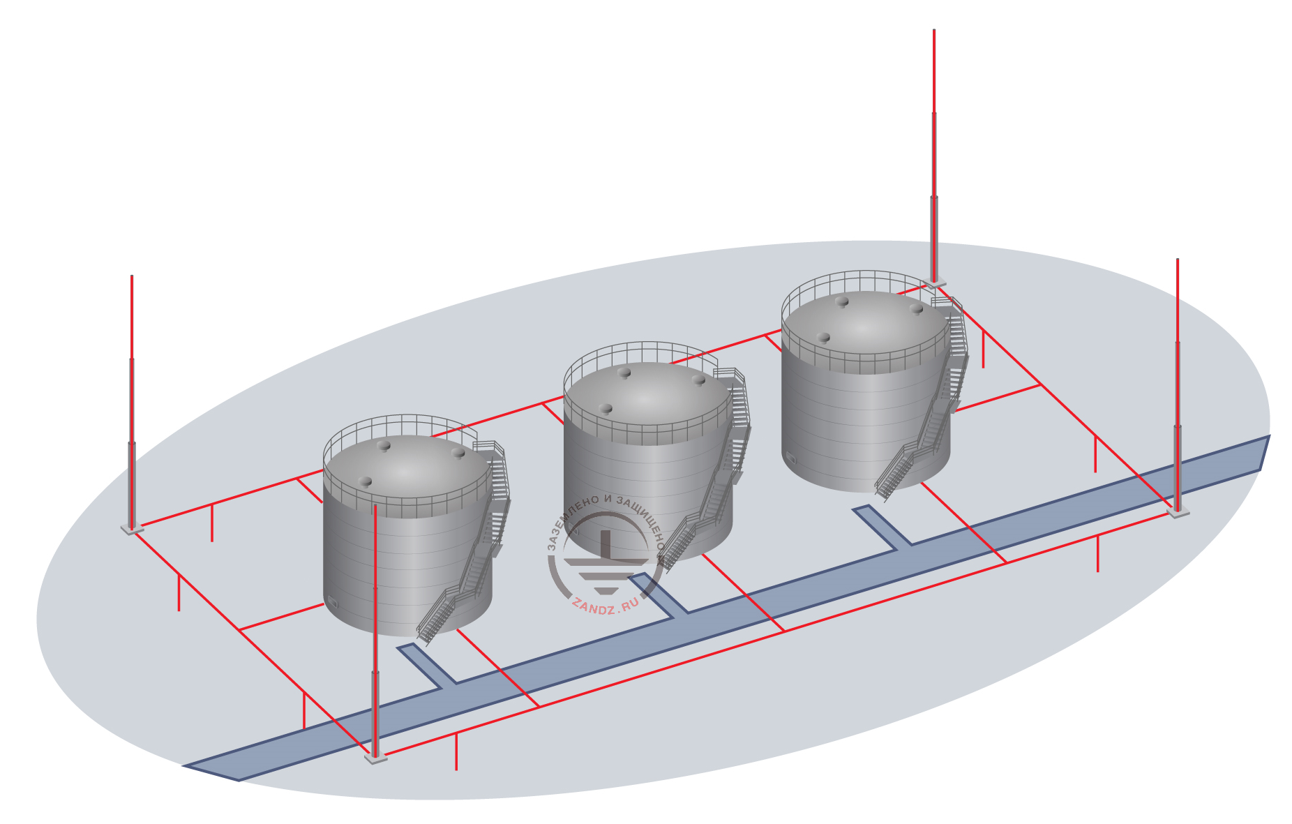 Oil storage tanks grounding and lightning protection project