Task
Facility: production building for chemical substances 12.2 x 6 x 6.75 m (L x W x H) In the protected building, in the course of technological processes in normal operating modes the gases in explosive levels emit, which are discharged in the atmosphere through the special openings. In accordance with the explosive hazard classification as per the Electrical Installation Code (EIC), the premises of the protected building are of Category В-I.
The specific soil resistivity: 100 Оhm·m.
The calculations and the design of the lightning protection system and the grounding device with resistance of 10 Ohms are required.
Solution
In accordance with the RD 34.21.122-87, the production building for chemical substances belongs to Category I of lightning protection and must be protected from the direct lightning strikes, their secondary effects, and import of high voltage via on-ground (above-ground) metal communications.|
Protection zone A is chosen in accordance with paragraph 1 of Table 1 of RD 34.21.122-87.
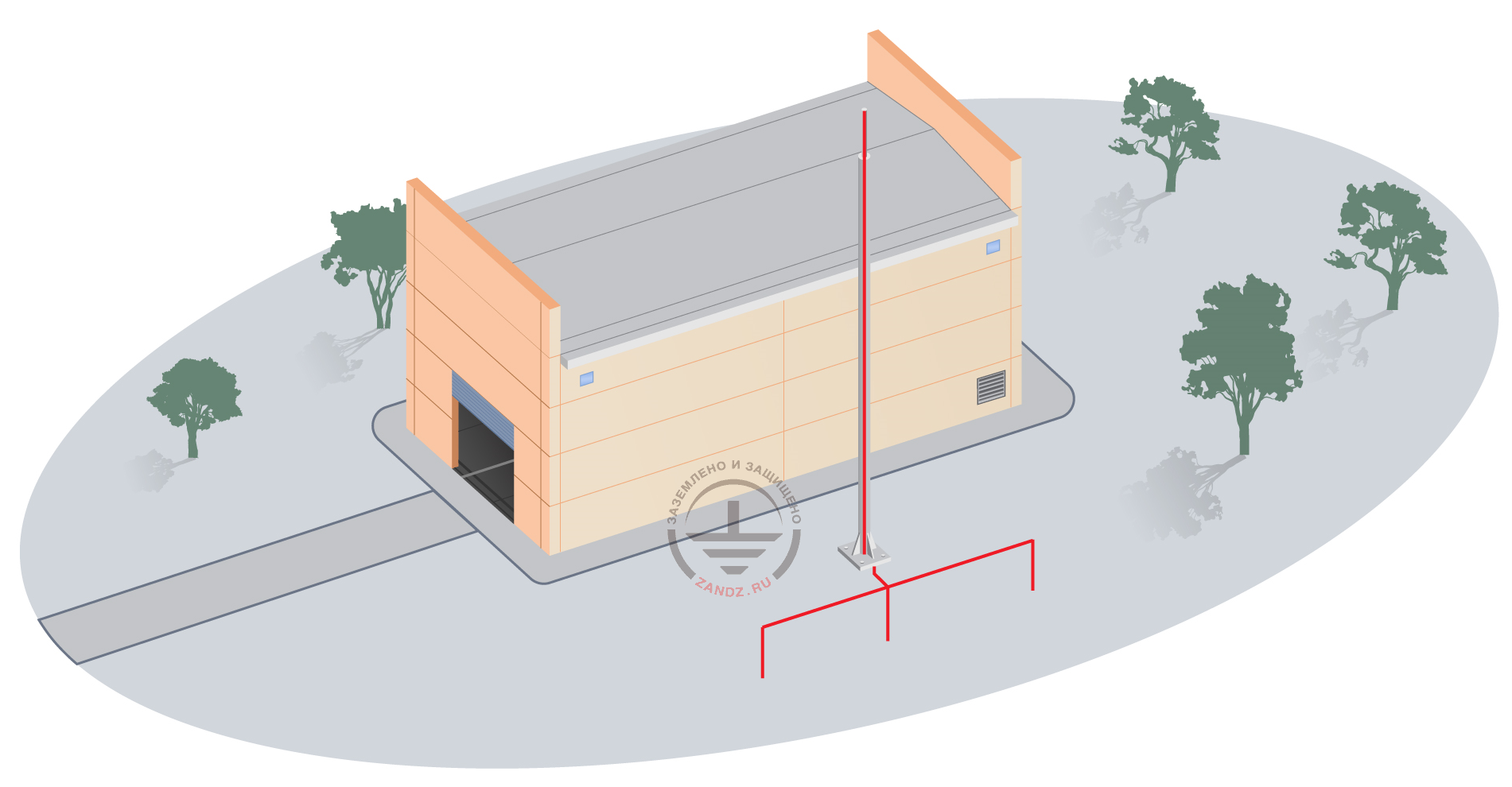
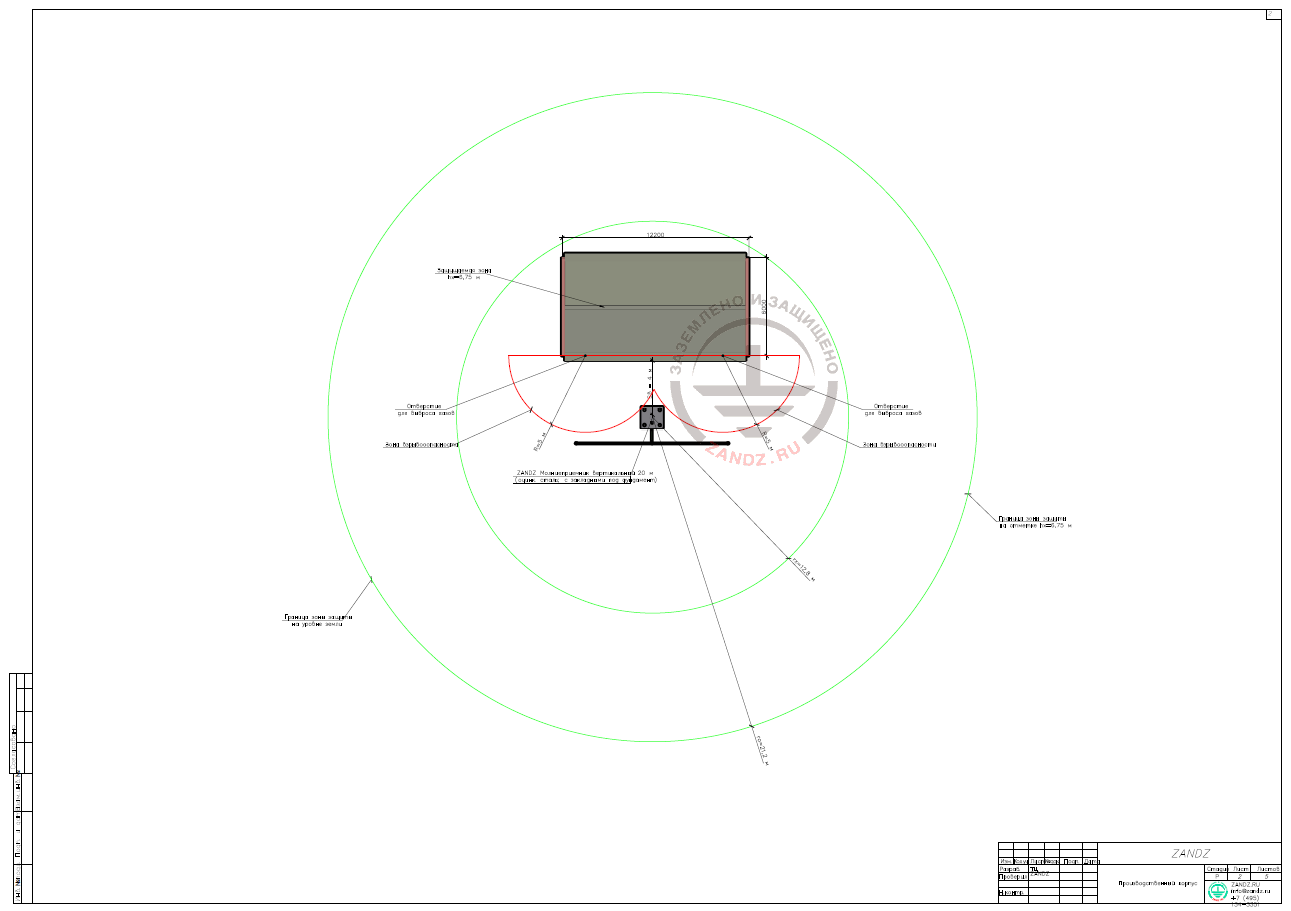
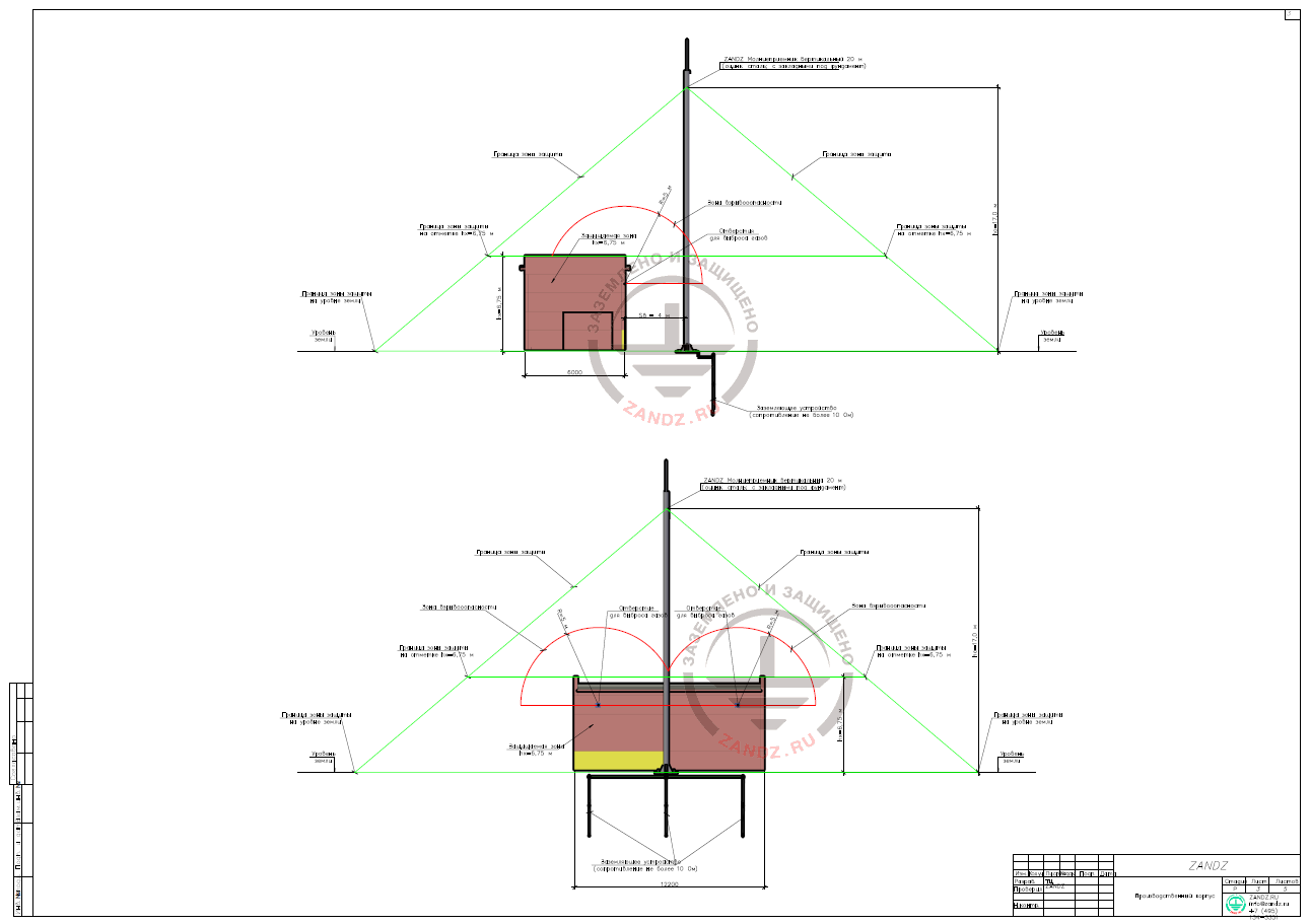
In accordance with paragraph 2.6 of RD 34.21.122-87, if there are straight gas outlet pipes and respiratory pipes on the buildings and structures for free disposal of gases, vapours, and explosive mixtures into the atmosphere, a space above the pipe cut limited by the hemisphere with the radius of 5 m must be covered by the protection zone. The protection from the secondary effects of lightning and import of high voltage is performed through the connection of metal columns of the production building to the existing protective grounding device of the building. The protection of the facility from direct lightning strikes is performed by using a vertical lightning rod 20 m ZANDZ ZZ-201-020 with the following dimensions:
ho = 0.85*h = 0.85*20 = 17.0 m is the height of the cone of the protection zone,
where h = 20 m is the lightning rod height;
ro = (1.1-0.002*h)* h = (1.1-0.002*20)*20 = 21.2 m is the cone radius at the ground level;
rx = (1.1-0.002*h)(h-hx/0.85) = (1.1-0.002*20)(20-6.75/0.85) = 12.8 m is the cone height at the level of the protected facility.
For boundaries of the protection zone, see drawings of this design.
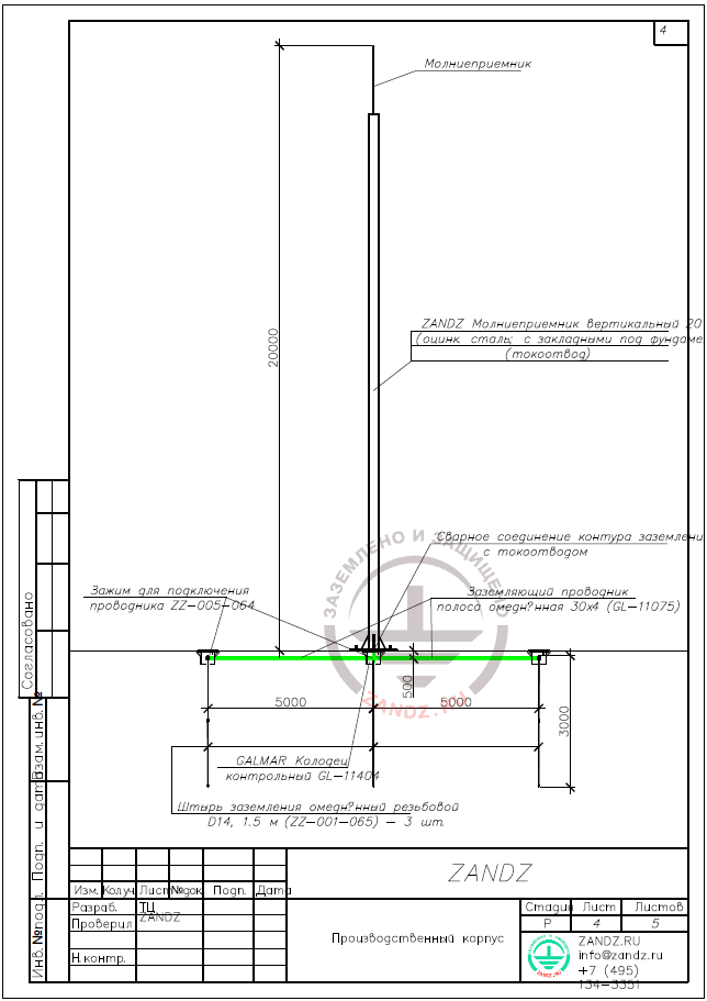
The grounding and lightning protection device for the production building consists of three vertical electrodes (copper-bonded threaded rods D14, 1.5 m ZZ-001-065, 2 pieces per 1 electrode) and copper-bonded tape 30x4 GL-11075 connected with the clamp for connecting ZZ-005-064 conductor in accordance with GOST 21130-75 (see the complete specification and links to the description of equipment below).
Carry out waterproofing for bolt connections and allow for inspecting connections at any time. Connect the grounding device to the lightning rod by welding. The grounding device is laid at the depth of 0.5 m from the ground surface and at the distance of 1 m from the lightning rod.
According to paragraph 3.2.2.5 of IS 153-34.21.122-2003, the own structure of vertical lightning rod 20 m high (galvanized steel; with embedded fittings for placing under the foundation) is used as a current collector. Electrical continuity between different parts is provided for a long term. The grounding device is arranged at the nearest territory outside the protection zone of the underground communications. Its precise location is determined during construction.
For arrangement of the grounding device, see drawings of this design.
Carry out installation of lightning protection and grounding according to EIC, ed. 7, AD 34.21.122-87 "Instructions for Lightning Protection of Buildings and Structures" and IS 153-34.21.122-2003 "Instructions for Lightning Protection of Buildings, Structures, and Industrial Communications", GOST 21130-75 "Electrical Items. Grounding Clamps and Signs. Design and Dimensions."
The resistance calculation for the grounding device
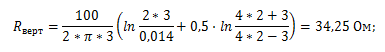
Vertical electrode resistance:
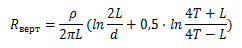
where p is the specific soil resistivity, Ohm·m;
L is the vertical electrode length, m;
d is the vertical electrode diameter, m;
T is the depth, the distance from the ground surface to the ground electrode, m.
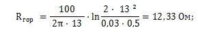
Horizontal electrode resistance:
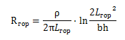
where ρ is the specific soil resistivity, Ohm·m;
b is the horizontal electrode band width, m;
h is the depth of the horizontal electrode burial, m;
Lгор is the horizontal electrode length, m.

where t is the depth of the electrode top, m.
Impedance of the grounding device:
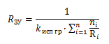
where n is the number of kits;
kисп is the utilization ratio.
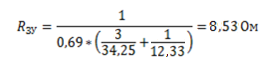
The design resistance of the grounding device is 8.53 Ohms, which is less than the permissible resistance of 10 Ohms.
The list of required materials:
| № | Fig. | Product item | Name | Quantity | Weight, unit, kg |
| 1. |  |
ZZ-001-065 | ZANDZ Copper-bonded threaded grounding rod (D14; 1.5 m) | 6 | 1,9 |
| 2. |  |
ZZ-002-061 | ZANDZ Threaded coupler | 4 | 0,08 |
| 3. |  |
GL-11703A | ZANDZ Starting tip | 3 | 0,07 |
| 4. |  |
ZZ-004-060 | ZANDZ Driving head for jackhammer | 2 | 0,09 |
| 5. |  |
ZZ-005-064 | ZANDZ Clamp for connecting conductor (up to 40 mm) | 3 | 0,31 |
| 6. |  |
ZZ-006-000 | ZANDZ Conductive grease | 1 | 0,19 |
| 7. |  |
ZZ-007-030 | ZANDZ Waterproof tape | 3 | 0,442 |
| 8. |  |
ZZ-008-000 | ZANDZ Head for jackhammer (SDS max) | 1 | 0,48 |
| 9. |  |
GL-11402 | GALMAR Inspection well | 3 | 2,6 |
| 10. |  |
GL-11075 | GALMAR Copper-bonded tape 30 x 4 mm | 13 | 0.98 (in meters) |
| 11. | 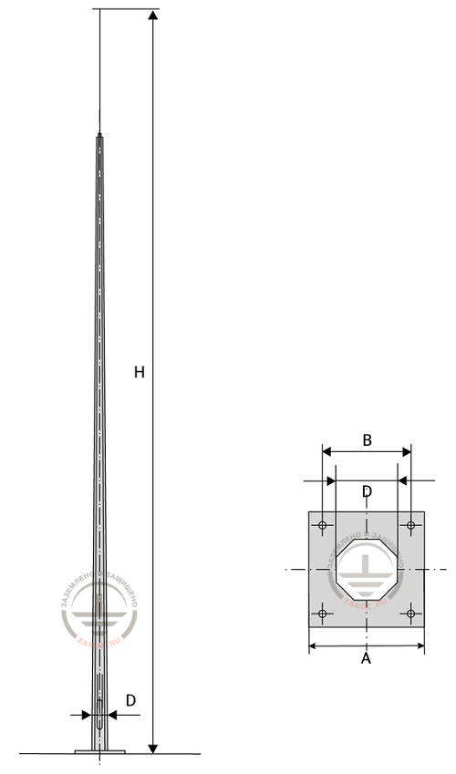 |
ZZ-201-020 | ZANDZ Vertical lightning rod 20 m (galvanized steel; with embedded fittings for placing under the foundation) | 1 | - |
Appendix: design is available in DWG and PDF formats
Do you need to design the grounding and lightning protection system? Order it by contacting the ZANDZ Technical Centre.
Related Articles: