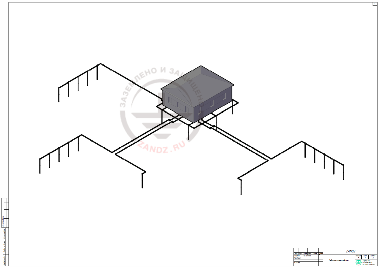
Открыть схему в полном размере
Task:
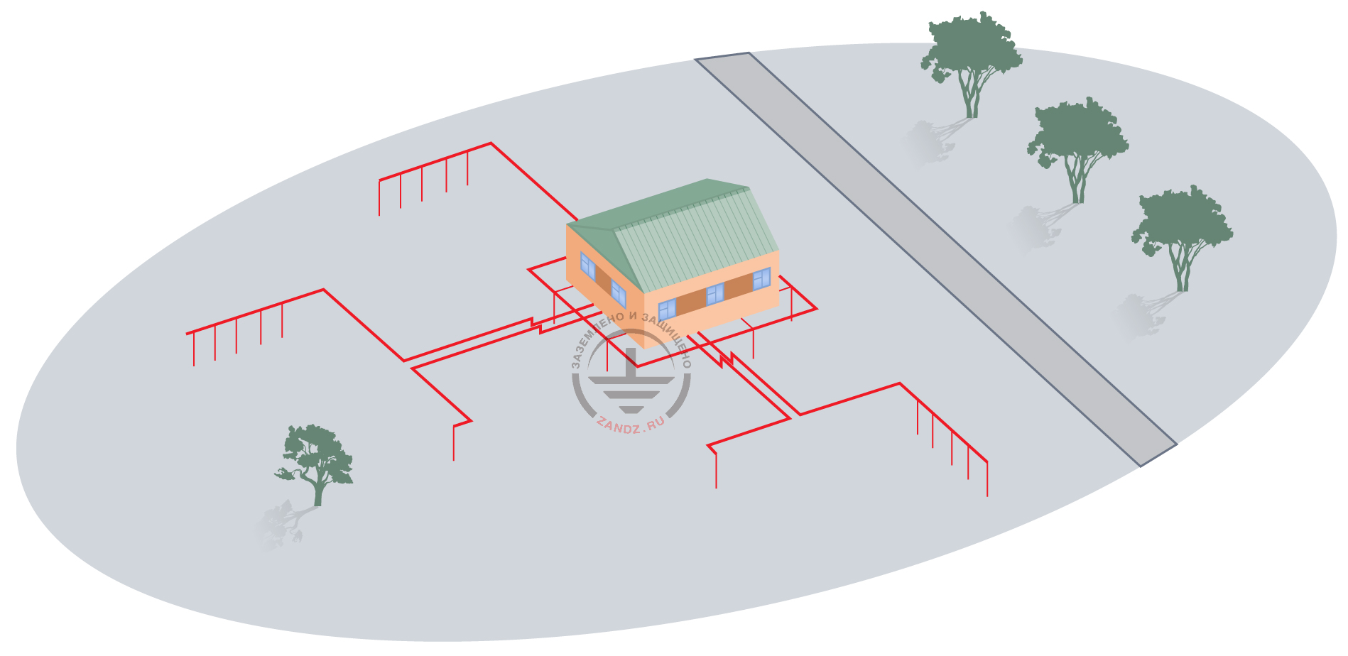
Facility: a wire broadcasting center 12.5 x 10 x 8 m (L x W x H).
Soil resistivity: 150 Ohm*m.
Make the calculations and design of lightning protection, protective earthing circuit, operating earthing circuits (functional earthing) for the DTE (data transmission equipment), ACC (area communication controller), EMI SHW (EMI shielding hardware), as well as two measuring ground terminals.
In accordance with c. 1.3 of GOST 464-79 the objects shall be equipped with independent operating and protective ground terminals in case of using remote Wire/Ground power supply circuits with earthing of the power source positive side.
According to the Terms of Reference, various operational earthing circuits are made separately.
In accordance with cc. 1.7, 2.1.3 of GOST 464-79 the resistance of the protective ground terminal and operating earthing circuits shall not exceed 30 Ohm, the resistance of the measuring ground terminal shall not exceed 200 Ohm - for the soils with resistivity over 100 Ohm*m.
Solution:
According to RD 34.21.122-87, the wire broadcasting station is classified as per category III of lightning protection and shall be protected against direct lightning strikes and high potential penetration through the above ground (overhead) metallic infrastructure.
Protection zone B is selected in line with item 7 of Table 1 of RD 34.21.122-87 and expected lightning strikes per year.
The protection against high voltage is performed by attaching metal columns of the wire broadcasting station building to the protective ground terminal. Columns have a continuous electrical connection to each other.
The expected number of the lightning strikes into the object per year is determined by the formula:
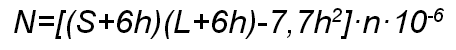
where h = 8 m s the highest object elevation;
L = 12,5 m is object length;
S = 10 m is object width;
n is lightning strike density per 1 km2 of the ground surface per year.
n = 6,7 · Тth/100, where Тth is the average thunderstorm duration in hours.
For Moscow Region the average thunderstorm duration is 20 to 40 hours.
Therefore:

The expected number of the lightning strikes into the object per year is 0,00606 strikes per year.
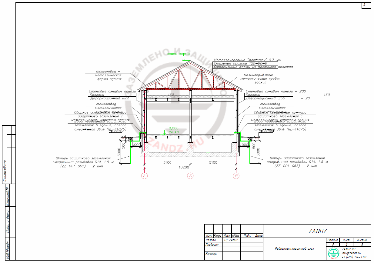
Because of no special requirements for the roofing protection against damages based on the metal thickness over 0.5 mm and no inflammable materials under roof, the natural lightning arrester is represented by the roof metallic structure refer to c.3.2.1.2 of SO 153-34.21.122-2003).
The building metallic columns welded to the metallic roofing framework are taken as conductors (refer to c. 3.2.2.5 of SO 153-34.21.122-2003).
A current collector (the building column) is connected to an external grounding circuit using a copper-plated bar 30 x 4 (GL-11075).
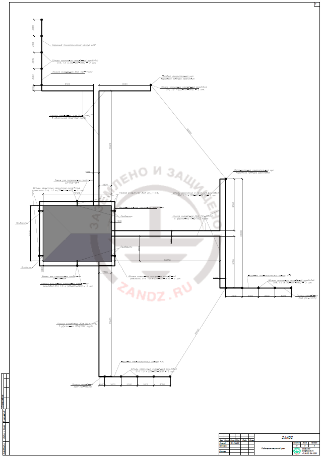
The external circuit of the protective earthing is made using 6 vertical electrodes (copper-plated threaded rods D14, 1.5 m ZZ-001-064 - 2 pcs per 1 electrode) interconnected by a 30 x 4 copper-plated strip GL-11075 using a clamp for connecting conductor ZZ-005-064. The ground terminal (the external circuit of the protective earthing) is installed at the depth of 0.5 m from the ground surface at the distance of 1 m from the building along its perimeter. The external earthing circuit is welded to the building columns with the spacing not exceeding 25 m.
According to item 1.7.55 of the EIC, the ground terminal for the lightning protection is combined with the external earthing circuit of electrical installations of the buildings. The protection against direct lightning strikes, secondary lightning effects, and high voltage is thus provided. See drawings attached hereto for the protective ground terminal structure.
Calculation of the ground terminal resistance:
The protective earthing circuit is calculated in accordance with Guidelines for Design, Construction, and Operations of the Earthing Systems in the Wired Communication Devices and Wireless Broadcasting Stations.
The estimated soil resistance is:
Рest. = Ohm*m
Freezing ratio:
for a vertical ground terminal, 1.8;
for a horizontal ground terminal, 4.5;
ηv = 0,66 (utilization ratio from Table 2.5, see Guidelines);
ηh = 0,40 (utilization ratio from Table 2.8, see Guidelines).
The distance between the electrodes L for a vertical ground terminal.
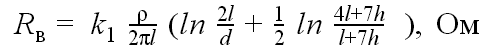
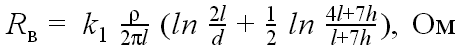
Vertical electrode resistance:
В - V
Ом - Ohm
where l is the length of the vertical ground terminal, m;
d – внешний диаметр вертикального заземлителя, м;
h is the outside diameter of the vertical ground terminal, m;
ρ is soil resistivity, Ohm×m;
k1 is the freezing coefficient, taking the seasonal soil temperature variations into account.

В - V
Ом - Ohm
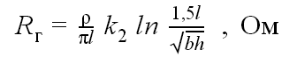
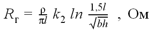
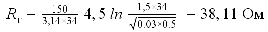
Resistance of the horizontal ground terminal:
Г- H
Ом - Ohm
where l is ground terminal length, m;
b is strip width, m;
h is strip depth, m;
ρ is soil resistivity, Ohm×m;
k2 is the freezing coefficient, taking the seasonal soil temperature variations into account.
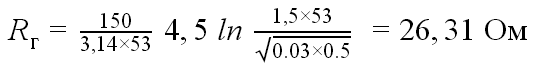
Г - H
Ом - Ohm
Estimated resistance of the multi-electrode ground terminal:
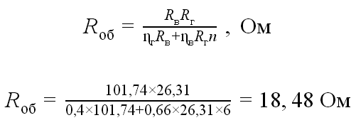
Estimated resistance of the protective ground terminal is 18.48 Ohm, which is less than the allowable resistance of 30 Ohm.
The design includes the engineering solutions with arrangement of the operating earthing circuits for DTE, ACC, EMI SHW, as well as two measuring ground terminals.
The operating earthing circuits are intended for provision of the radio broadcasting station equipment normal operation, enabling reduction of the electromagnetic emissions and external interferences influence on the equipment.
According to the calculation data, each process circuit of the operational earthing is made of 5 vertical electrodes (copper-plated threaded rods D14, 1.5 m ZZ-001-065 - 2 pcs per 1 electrode) and 30 x 4 copper-plated strip GL-11075, connected using a clamp for connecting conductors ZZ-005-064 (see below for full specifications and references to the equipment description). The current and potential measuring ground terminals are made of 1 vertical electrode (threaded copper-plated rod D14, 1.5 m ZZ-001-065 - 2 pcs. per 1 electrode) and copper-plated strip 30х4 GL-11075, connected through the clamp ZZ-005-064 for conductor connection (full specifications and references to the hardware description are given below).
The inspection pits (GL-11402) are provided for controlling the locations of the ground terminals connection to the earthing conductors and for making control resistance measurements of the ground terminal. External operating earthing circuits and measuring probes are connected to the radio broadcasting station's DTE, ACC, EMI SHW earthing shield busbars through the 30х4 copper-plated strip (GL-11075).
A waterproofing shall be made for the bolted joints, which joints shall be accessible for the inspection at any moment.
For the arrangement of the external operating earthing circuits refer to the drawings of this design.
The lightning protection, protective earthing circuit, operating earthing circuits of DTE, ACC, EMI SHW, as well as two measuring ground terminals shall be installed in accordance with EIC, Rev. 7, RD 34.21.122-87 "Guidelines for making the lightning protection of buildings and structures", SO 153-34.21.122-2003 "Guidelines for making the lightning protection of buildings, structures and industrial infrastructure", GOST 464-79 "Earthing of the fixed wire communication installations, radio relay stations, wire broadcasting stations and the community reception television antennas. Standards for resistance", "Guidelines for design, construction and operation of earthing in the wire communication installations and radio broadcasting stations", GOST 21130-75 "Electrotechnical products. Earthing clamps and earthing signs. Design and size".
Calculation of resistance of operating ground terminals:
The operating earthing circuit calculation was made in accordance with the "Guidelines for design, construction and operation of earthing in the wire communication installations and radio broadcasting stations".
The estimated soil resistance is:
Рest = 150 Ohm*m
Freezing ratio:
for a vertical ground terminal, 1.8;
for a horizontal ground terminal, 4.5;
ηv = 0,66 0.66 (utilization ratio from Table 2.5, see Guidelines);
ηh = 0,40 (utilization ratio from Table 2.8, see Guidelines).
The distance between the electrodes L for a vertical ground terminal.
Vertical electrode resistance:
where l the length of the vertical ground terminal, m;
d is the outside diameter of the vertical ground terminal, m;
h is the distance from the ground surface to the top end of the vertical ground terminal, m;
ρ is soil resistivity, Ohm×m;
k1 is the freezing coefficient, taking the seasonal soil temperature variations into account.

В - V
Ом - Ohm
Resistance of the horizontal ground terminal:
Г - H
Ом - Ohm
where l is ground terminal length, m;
b is strip width, m;
>h is strip depth, m;
ρ is soil resistivity, Ohm×m;
k2 is the freezing coefficient, taking the seasonal soil temperature variations into account.
Г - H
Ом - Ohm
Estimated resistance of the multi-electrode ground terminal:
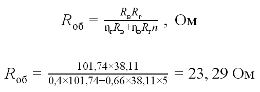
Estimated resistance of the ground terminal is 23.29 Ohm, which is less than allowable resistance of 30 Ohm.
Measuring probe resistance:
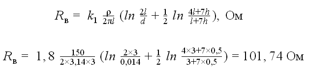
В - V
Ом - Ohm
Estimated resistance of a measurement ground terminal is 101.74 Ohm, which is less than allowable resistance of 200 Ohm.
List of required materials:
| Item # | Fig. | Designation | Name | Quantity | Weight (kg per unit) |
| 1 |  |
ZZ-001-065 | ZANDZ Threaded copper-plated grounding rod (D14; 1.5 m) | 46 | 1,9 |
| 2 |  |
ZZ-002-061 | ZANDZ Threaded connecting coupling | 23 | 0,08 |
| 3 |  |
ZZ-003-061 | ZANDZ Kick-off tip | 23 | 0,07 |
| 4 |  |
ZZ-004-060 | ZANDZ Guide head for jackhammer attachment | 10 | 0,09 |
| 5 |  |
ZZ-005-064 | ZANDZ Clamp for connecting conductors (up to 40 mm) | 50 | 0,31 |
| 6 |  |
ZZ-006-000 | ZANDZ Conductive grease | 7 | 0,19 |
| 7 |  |
ZZ-007-030 | ZANDZ Waterproof tape | 10 | 0,442 |
| 8 |  |
ZZ-008-000 | ZANDZ Attachment to the hammer (SDS max) | 1 | 0,48 |
| 9 |  |
GL-11402 | GALMAR Inspection pit | 23 | 2,6 |
| 10 |  |
GL-11075 | GALMAR copper-plated steel strip 30х4 mm | 250 | 0,98 (in meters) |
| 11 | — | Anchor wedge 6х60 mm | 150 | ||
| 12 | — | Double wall pipe LDPE/HDPE Т2-КЛ0-050К, d = 50 mm, Dint = 40 mm | 160 | (in meters) |
Appendix: design in DWG and PDF formats
 |
 |
 |
Need a design of earthing and lightning protection? Order now by contacting ZANDZ Technical Center!
Related Articles:
