Task:
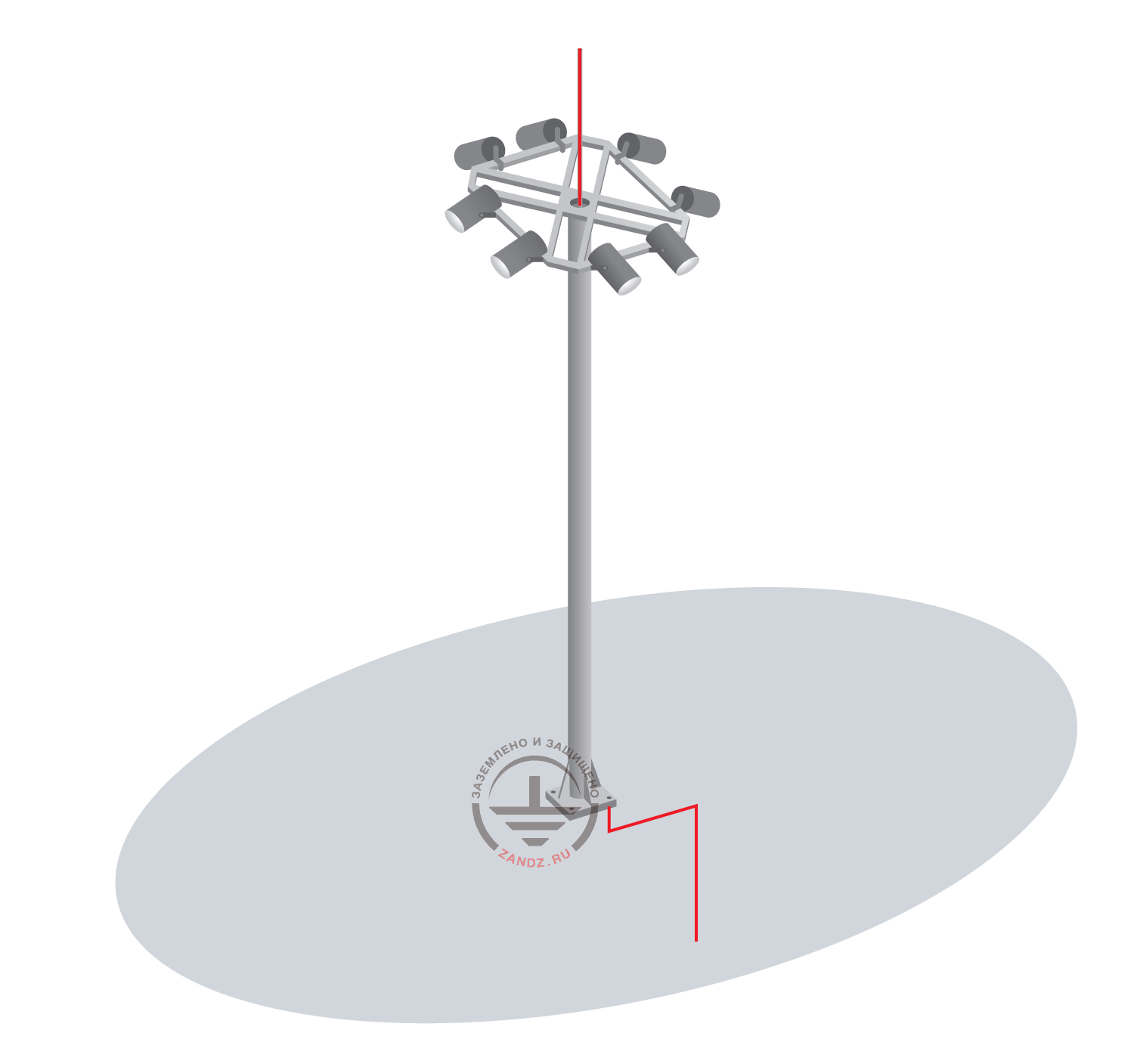
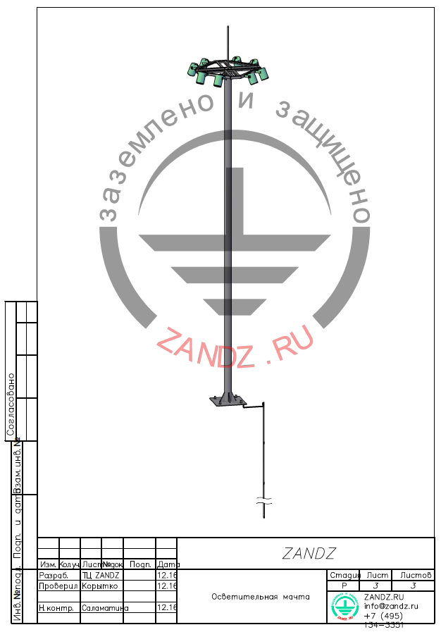
Object: free-standing metal light post of a flange type.
The post presents itself a fully-metal construction 16 m high and 300 mm in diameter. The base of the mast is covered with flange fixation for 4 holes. Insite the post is empty, it is possible to run wires inside.
In the bottom part of the post there is a section for commutation of internal electric lines of the post. The post is mounted on its own concrete fundation with flange embedded details. Fixation of the post to the foundation is carried out by bolt connections.
Soil resisitivity: 100 Ohm*m
Solution:
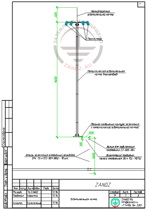
According to the calculation data, the grounding contour is made of 1 vertica electrode (copper-bonded threaded rods D14, 1.5m ZZ-001-065 10 pieces per 1 electrode) and copper-bonded tape 30x4 GL-11075 connected with the help of the clamp for connecting conductor ZZ-005-064 (see full specification and links to the description of equipment below).
Carry out hydroinsulation for bolt connections and foresee the possibility of inspection of connections at any time.
Connect the grounding contour to the metal base of the post by welding.
The grounding device (grounding contour) is laid at the depth of 0,5 m from the ground surface at the distance of 1 m from the light post.
Lightning rod is foreseen by the post design.
The own construction of the mast and internal down conductor, connected with the construction of the mast and its coupling in accordance with p. 3.2.2.5 IS 153-34.21.122-2003, are acting as a down conductor. Electric continuity between the different parts is provided for a long term.
The grounding contour is organized at the nearest territory outside the protective zone of underground communications, its precise location is defined when building it.
Arrangement of the external grounding contour, see the layouts of the present project.
Carry out installation of lightning protection and grounding according to EIC, ed. 7, AD 34.21.122-87 "Instructions for lightning protection of buildings and structures" and IS 153-34.21.122-2003 "Instructions for lightning protection of buildings, structures and industrial communications".
Calculation of grounding device resistance:
Calculation of grounding for a single deep-laid ground electrode on the base of modular grounding is carried out as calculation of an ordinary vertical ground electrode of metal rod with the diameter of 14 mm:
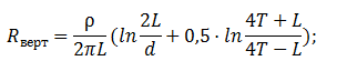
where ρ - equivalent soil resistivity, ohm · m;
L - length of the vertical electrode, m;
d - vertical electrode diameter, m;
T- deepening - distance from the ground surface to the ground electrode, m;
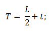
where t - deepening of the electrode top, m
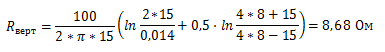
Contribution of the connecting ground conductor is not taken into account here. The design resistance of the grounding device is 8.68 ohms, which is less than the permissible resistance of 10 ohms.
The list of required materials:
| № | Fig. | Designation | Name | Q-ty | Weight, unit, kg |
| 1 |  |
ZZ-001-065 | ZANDZ Copper-bonded threaded grounding rod (D14; 1,5 m) | 10 | 1,9 |
| 2 | 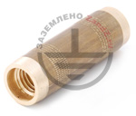 |
ZZ-002-061 | ZANDZ Threaded coupler | 10 | 0,08 |
| 3 | 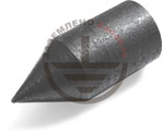 |
ZZ-003-061 | ZANDZ Starting tip | 1 | 0,07 |
| 4 | 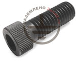 |
ZZ-004-060 | ZANDZ Driving head for a breaker hammer | 2 | 0,09 |
| 5 | 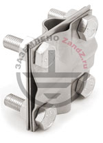 |
ZZ-005-064 | ZANDZ Clamp for connecting conductor (up to 40 mm) | 1 | 0,31 |
| 6 | 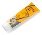 |
ZZ-006-000 | ZANDZ Conductive grease | 1 | 0,19 |
| 7 | 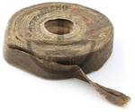 |
ZZ-007-030 | ZANDZ Water-proof tape | 1 | 0,442 |
| 8 |  |
ZZ-008-000 | ZANDZ Driving head for a breaker hammer (SDS max) | 1 | 0,48 |
| 9 | 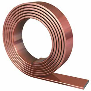 |
GL-11075 | GALMAR copper bonded tape 30x4 mm | 2 | 0,98 (in meters) |
| 10 | 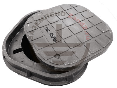 |
GL-11402 | GALMAR Inspection pit | 1 | 2,6 |
Appendix: the project is available in DWG and PDF formats
Do you need to make the project on grounding and lightning protection? Contact ZANDZ Technical Centre!
Related Articles:
